Physical Installation Instructions for PCIe* NVMe* U.2 and Add-In Card Solid State Drives
Content Type: Install & Setup | Article ID: 000026843 | Last Reviewed: 11/07/2022
See the instructions below for how to properly install an SSD (Add-in Card or U.2 2.5 inch form factor) that uses the PCIe* NVMe* interface.
For proper handling and installation instructions for an M.2 form factor drive, see the Proper Handling Techniques and Precautions for Your M.2 Device.
The PCIe* NVMe* interface requires specific motherboard or system vendor support, so confirm with your vendor before proceeding.
Caution | Disconnect/unplug the system's power supply from its AC power source before you connect cables, disconnect cables, install, or remove any board components. If a laptop is being used, remove the battery as well if possible per your vendor's instructions Without first disconnecting the power supply, you risk personal injury or equipment damage. Some circuitry on the desktop board can operate even if the front panel power switch is off. Electrostatic discharge (ESD) can damage desktop board components. Install the board at an ESD-controlled workstation. If an ESD-controlled workstation is unavailable, wear an anti-static wrist strap or touch the surface of the anti-static package before handling the board. |
Your board may have multiple PCIe* slots. The PCIe SSD needs a PCI Express* (PCIe) x4 or higher connector. Best performance is with a PCIe 3.0 connector.
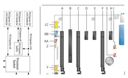
In our example:
See your chassis manual for more detailed instructions.
See your chassis manual for more detailed instructions.
| M.2 | 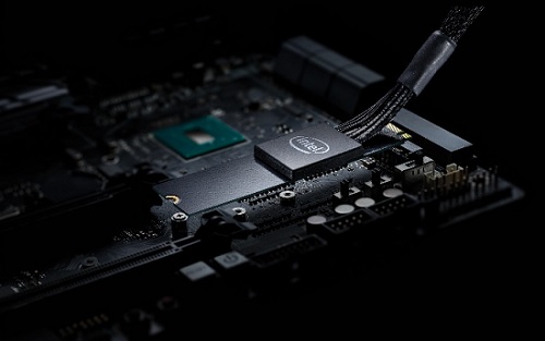 |
| SFF 8643 | 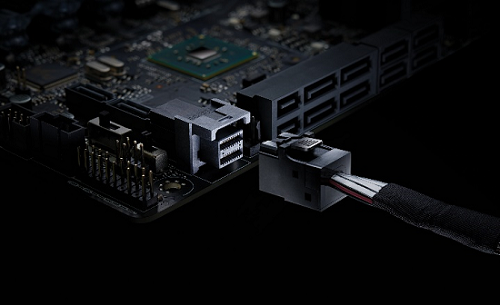 |
| Note |
|