2.6.1. GTS Transceiver Toolkits Debugging Feature
Use this feature to debug the GTS transceiver link running on your board. For example, you can use this feature to debug video symbol or alignment lock stable for RX and external SDI link flickering cases for TX. The GTS Transceiver Toolkit Debugging feature is not supported for Agilex™ 5 dual simplex design. Currently, SDI only supports excluded transceiver (Excluded PHY) and non-dual simplex (Non-DS) designs.
To enable the GTS Transceiver Toolkit, follow these steps:
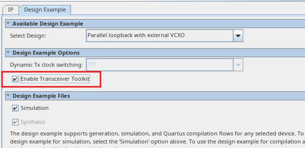
- Click on Enable Transceiver Toolkit in the Design Example tab under Design Example Options.
- After selecting Enable Transceiver Toolkit, you can proceed to generate the design example.
- Compile the Design and Program SOF file to the board.
- Launch the System Debugging Toolkits (by selecting Tools > System Debugging Tools > System Debugging Toolkits).
- Transceiver links are identified automatically and displayed in the Toolkit Explorer.
In the Collection status table, select the pins for the RX and TX channels.
Figure 30. Pin RX and TX Channels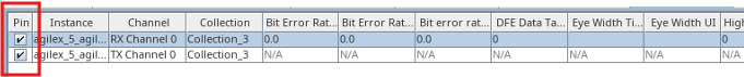
You can set TX Equalization Parameters in the TX Channel Parameters tab. Load the values by selecting Get Parameters or key in the values by selecting Set Parameters.
Figure 31. Set TX Equalization Parameters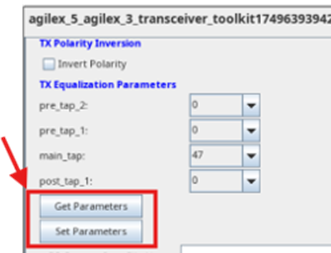
Check the TX PLL Locked signal status.
Figure 32. TX PLL Lock Signals for TX Channel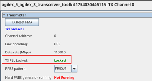
You can set the RX PMA Settings in the RX Channel Parameters tab. Load the values by selecting Refresh Parameters or key in the values by selecting Set Parameters.
Figure 33. Set RX Equalization Parameters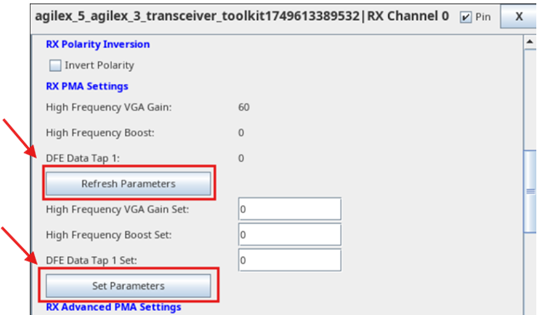
- After setting the value, click on Refresh Parameters to update values of the RX PMA Settings.
Check RX CDR locked to ref clock signal and RX CDR locked to data signal in the RX tab.
Figure 34. RX CDR Lock Signals for RX Channel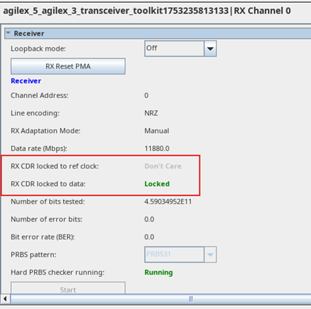
- Repeat tuning the parameters until the video lock signal becomes stable for RX and no flickering issues for TX.
- Hard PRBS generator in TX and Hard PRBS checker in RX are only supported in Static Rate Design. Other designs support will be enabled in future releases.
- To enable the Internal PRBS checker, follow these steps:
- Hardware connection—connect RX to TX loopback.
- In the RX top-level file, uncomment out the lines and comment out rst_trig_rst for sdi_rx_phy_inst|i_rx_reset.
- Recompile the design again and repeat step 4 to step 13.
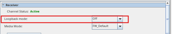
Before running the PRBS checker, ensure the Loopback mode in the RX channel is turned Off.
Figure 35. Loopback Mode in RX Channel