5. Containerized FPGA AI Suite SoC Design Example Quick-Start Tutorial
This quick-start tutorial demonstrates how you can run the FPGA AI Suite SoC design example quick-start tutorial in a containerized FPGA AI Suite instance.
When running the container, the environment for FPGA AI Suite, OpenVINO™ , and Python environment (openvino_env) are all set for you when the container is started.
- Set up the FPGA AI Suite Docker* image.
For instructions refer to Setting Up the FPGA AI Suite Docker Image.
- Start the FPGA AI Suite Docker* container.
For instructions, refer to Running the FPGA AI Suite Docker Container.
Starting the container sets all the required environment variables, including the CODEDLA_WORK and COREDLA_ROOT environment variables.
The remaining steps are performed in the Windows command prompt session that you start in this step.
- Confirm that the FPGA AI Suite compiler is working correctly by running the following command:
dla_compiler \
     --march $COREDLA_ROOT/example_architectures/AGX7_Performance.arch \
     --fanalyze-area
This command should generate output similar to the following example output:Exporting input transform to file Exporting output transform to file Executing area estimate Estimated area: ALMs: 56186 ALUTs: 59999 Registers: 217674 DSPs: 602 M20Ks: 1209 Memory ALMs: 2426
- Create a working directory for the FPGA AI Suite SoC example design files and copy the files into the working directories:
mkdir ~/coredla_work && cd coredla_work

source dla_init_local_directory.sh
The FPGA AI Suite SoC example design files include precompiled bitstreams and SD card image files. Instructions for compiling the SD card image are provided later on.- Agilex™ 7 FPGA I-Series Transceiver-SoC Development Kit
The files for this development kit will be in in the following location:
~/coredla_work/demo/ed4/agx7_soc_s2m
The set of Agilex™ 7 FPGA I-Series Transceiver-SoC Development Kit files include the following files in subfolders:- bitstream subfolder:
AGX7_FP16_Generic/
AGX7_Performance/
AGX7_Small_NoSoftmax/
- sd-card subfolder:
coredla-image-agilex7_dk_si_agi027fa.cpio
u-boot-spl-dtb.hex.jic
coredla-image-agilex7_dk_si_agi027fa.wic
u-boot-spl-dtb.hex.sof
u-boot-spl-dtb.hex0
- bitstream subfolder:
- Arria® 10 SX SoC FPGA Development Kit
The files for this development kit will be in in the following location:
~/coredla_work/demo/ed4/a10_soc_s2m
The set of Arria® 10 SX SoC FPGA Development Kit files include the following files in subfolders:- bitstream subfolder:
A10_FP16_Generic/
A10_Performance/
A10_Small_NoSoftmax/
- sd-card subfolder:
coredla-image-arria10.cpio
coredla-image-arria10.wic
- bitstream subfolder:
- Agilex™ 7 FPGA I-Series Transceiver-SoC Development Kit
- Build the SD card image:
Tip: Alternatively, you use the .wic files provided in the sd-card subfolders (as shown in the previous step) and skip this step.
- Navigate to the runtime folder with the following command:
cd ~/coredla_work/runtime/
- Build the image for your development kit with one of the following commands:
- Agilex™ 7 FPGA I-Series Transceiver-SoC Development Kit
./create_hps_image.sh \
 -f ~/coredla_work/demo/ed4/agx7_soc_s2m/bitstreams/AGX7_Performance/ \
 -o ../sd-card -u \
 -m agilex7_dk_si_agi027fa
- Arria® 10 SX SoC FPGA Development Kit
./create_hps_image.sh \
-f ~/coredla_work/demo/ed4/a10_soc_s2m/bitstreams/A10_Performance/ \
-o ../sd-card -u \
-m arria10
If either of these commands fails with an error message about being unable to clone the linux-socfpga-lts package, complete the following steps:- Review the error messages to determine the branch version of the linux-socfpga-lts repository required. Look for an error message similar to the following message:
ERROR: linux-socfpga-lts-6.6.22-lts-git-r0 do_fetch
In this example message, the branch version is 6.6.22.
- Run the following commands:
rm -rf ~/coredla_work/runtime/build_Yocto

git clone https://github.com/altera-opensource/linux-socfpga.git \
    -b socfpga-<version>-lts \
    ~/coredla_work/runtime/build_Yocto/build/downloads/git2/github.com.altera-opensource.linux-socfpga.git
where <version> is the branch version you determined earlier. - Run the create_hps_image.sh command again.
- Agilex™ 7 FPGA I-Series Transceiver-SoC Development Kit
- Navigate to the runtime folder with the following command:
- [FPGA] Prepare the SD card for the FPGA development kit:
- Write the SD card image to an SD card:
- Open Win32 Disk Imager. The UI looks like the following image:
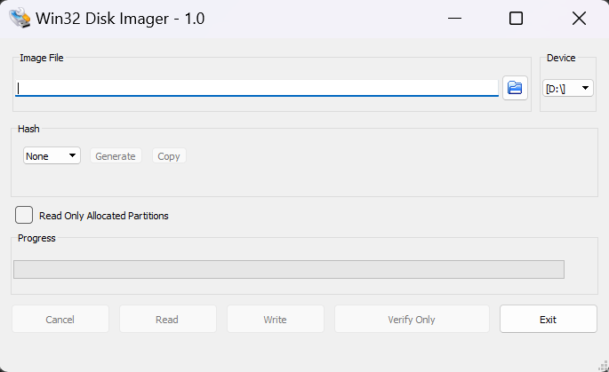
- Select the SD card device and then click the folder icon to open the File Explorer to select the .wic image to image the SD card with.
The .wic image to specify is found in the folder that you specified as part of the docker command -v option when you followed the instructions in Running the FPGA AI Suite Docker Container. In this case, the folder is C:\Users\<username>\<path-to-share>:/mnt/host fpga-ai-suite: 2024.3.

- Click Write and then click Yes in the pop-up window.
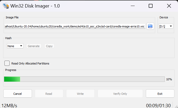
- Open Win32 Disk Imager. The UI looks like the following image:
- Eject the SD card device properly from Windows* to avoid any data corruption.
- Ensure the FPGA development kit is powered off and insert the SD card into the FPGA development kit SD card slot.
- Write the SD card image to an SD card:
- [FPGA] Prepare and program the FPGA development kit:
- Agilex™ 7 FPGA I-Series Transceiver-SoC Development Kit
- With FPGA development kit powered off, set switch S9 to [ON/ON/ON/X] to program the .jic file to the FPGA.
- Power on the development kit.
- Move the .jic file to the host with the following command:
cp ~/coredla_work/sd-card/u-boot-spl-dtb.hex.jic \
   /mnt/c/Users/<user>/Downloads/
- In a Windows* command prompt session, verify that the host system recognizes the FPGA development kit board with the following command:
C:\intelFPGA_pro\24.3\qprogrammer\quartus\bin64\quartus_pgm.exe -m jtagTake note of the cable/device number in the output of this command. You need this number in the next step.
- Program the FPGA device by running the following command at a Windows* command prompt:
C:\intelFPGA_pro\24.3\qprogrammer\quartus\bin64\quartus_pgm.exe \ -m jtag \ -c <cable_number><device_number>" - Power off the development kit and set switch S9 to [ON/OFF/OFF/X] to set the development kit board in fast mode.
- Power on the development kit.
- Arria® 10 SX SoC FPGA Development Kit
Not required.
- Agilex™ 7 FPGA I-Series Transceiver-SoC Development Kit
- Obtain the FPGA development kit host name and IP address:
- With the FPGA development kit powered on, start a minicom session from the Windows* command prompt session where you started the container. Run the following command to start a minicom session:
sudo minicom
- In the minicom session, run the following command to get the host name of the FPGA development kit:
hostname
- In the minicom session, run the following command to get the IP address of the FPGA development kit:
ping <hostname>.local –c4
Where <hostname> is the host name you obtained in the previous step.
- With the FPGA development kit powered on, start a minicom session from the Windows* command prompt session where you started the container. Run the following command to start a minicom session:
- Install OpenVINO™ Model Zoo:
- Start an Ubuntu command line session.
- In the command line session, run the following commands:
cd ~/coredla_work/demo

git clone https://github.com/openvinotoolkit/open_model_zoo.git

cd open_model_zoo

git checkout 2023.3.0
- Generate IR files for FPGA AI Suite using the OpenVINO™ Model Optimizer with the following commands:
omz_downloader --name resnet-50-tf \
  --output_dir $COREDLA_WORK/demo/models/

omz_converter --name resnet-50-tf \
  --download_dir $COREDLA_WORK/demo/models/ \
  --output_dir $COREDLA_WORK/demo/models/
These commands result in the following IR files:- resnet-50-tf.bin
- resnet-50-tf.xml
- resnet-50-tf.mapping
- Compile the model for use on the FPGA device with the FPGA AI Suite compiler. The precompiled SD card image (.wic) provided with the FPGA AI Suite uses one of the following files as the IP architecture configuration file:
- Agilex™ 7 FPGA I-Series Transceiver-SoC Development Kit
AGX7_Performance.arch - Arria® 10 SX SoC FPGA Development Kit
A10_Performance.arch
To create the AOT file for the M2M variant (which uses the dla_benchmark utility), run the following command:cd $COREDLA_WORK/demo/models/public/resnet-50-tf/FP32 dla_compiler \ --march $COREDLA_ROOT/example_architectures/<IP arch config file> \ --network-file ./resnet-50-tf.xml \ --foutput-format=open_vino_hetero \ --o $COREDLA_WORK/demo/RN50_Performance_b1.bin \ --batch-size=1 \ --fanalyze-performance
where <IP arch config file> is one of the IP architecture configuration files listed earlier.
To create the AOT file for the S2M variant (which uses the streaming inference app), run the following command:cd $COREDLA_WORK/demo/models/public/resnet-50-tf/FP32 dla_compiler \ --march $COREDLA_ROOT/example_architectures/<IP arch config file> \ --network-file ./resnet-50-tf.xml \ --foutput-format=open_vino_hetero \ --o $COREDLA_WORK/demo/RN50_Performance_no_folding.bin \ --batch-size=1 \ --fanalyze-performance \ --ffolding-option=0
where <IP arch config file> is one of the IP architecture configuration files listed earlier.
After running either these commands, the compiled models and demonstration files are in the following locations:
Compiled Models
$COREDLA_WORK/demo/RN50_Performance_b1.bin
$COREDLA_WORK/demo/RN50_Performance_no_folding.bin
Sample Images
$COREDLA_WORK/demo/sample_images/
Architecture File
$COREDLA_ROOT/example_architectures/AGX7_Performance.arch
or
$COREDLA_ROOT/example_architectures/A10_Performance.arch
- Agilex™ 7 FPGA I-Series Transceiver-SoC Development Kit
- (Optional) At this point, you can also try one of the following flows before continuing:
- Copy the required demonstration files to the /home/root/resnet-50-tf folder on the SD card:
- In the minicom session, create directories to receive the model data and sample images:
mkdir ~/resnet-50-tf
- On the development host, use the secure copy (scp) command to copy the data to the board:
TARGET_IP=<Development Kit Hostname>.local

TARGET=”root@$TARGET_IP:~/resnet-50-tf”

demodir=$COREDLA_WORK/demo

scp $demodir/*.bin $TARGET/.

scp -r $demodir/sample_images/ $TARGET/.

scp $COREDLA_ROOT/example_architectures/<architecture file> $TARGET/.

scp $COREDLA_ROOT/build_os.txt $TARGET/../app/
where <architecture file> is one of the following files, depending on your development kit:- Agilex™ 7 FPGA I-Series Transceiver-SoC Development Kit
AGX7_Performance.arch - Arria® 10 SX SoC FPGA Development Kit
A10_Performance.arch
- Agilex™ 7 FPGA I-Series Transceiver-SoC Development Kit
- [Optional] In the minicom session, run the sync command to ensure that the data is flushed to disk.
- In the minicom session, create directories to receive the model data and sample images:
- Verify the FPGA development kit device drivers. The device drivers should be loaded when the HPS boots.
Verify that the device drivers are initialized by checking that uio files are listed in /sys/class/uio by running the following command:
ls /sys/class/uio
The command should show output similar to the following example:uio0 uio1 uio2
If the drivers are not listed, refresh the modules by running the following command before checking again that the drivers are loaded:uio-devices restart
- Run one of the demonstration applications:
-
Run the M2M demonstration application
The M2M data flow model uses the dla_benchmark demonstration application. The S2M bitstream supports both the M2M data flow model and the S2M data flow model.
You must know the host name of the FPGA development kit that you determined in an earlier step.
To run inference on the FPGA development kit:- Open an SSH connection to the FPGA development kit:
- Start a new terminal session
- Run the following command:
build-host:$ ssh <devkit_hostname>
- In the SSH terminal, run the following commands:
export compiled_model=~/resnet-50-tf/RN50_Performance_b1.bin

export imgdir=~/resnet-50-tf/sample_images

export archfile=~/resnet-50-tf/<architecture file>

cd ~/app

export COREDLA_ROOT=/home/root/app

./dla_benchmark \
   -b=1 \
   -cm $compiled_model \
   -d=HETERO:FPGA,CPU \
   -i $imgdir \
   -niter=5 \
   -plugins_xml_file ./plugins.xml \
   -arch_file $archfile \
   -api=async \
   -groundtruth_loc $imgdir/TF_ground_truth.txt \
   -perf_est \
   -nireq=4 \
   -bgr
where <architecture file> is one of the following files, depending on your development kit:- Agilex™ 7 FPGA I-Series Transceiver-SoC Development Kit
AGX7_Performance.arch - Arria® 10 SX SoC FPGA Development Kit
A10_Performance.arch
- Agilex™ 7 FPGA I-Series Transceiver-SoC Development Kit
The dla_benchmark command generates output similar to the following example output for each step:[Step 11/12] Dumping statistics report count: 8 iterations system duration: 174.3530 ms IP duration: 112.1184 ms latency: 79.9449 ms system throughput: 45.8839 FPS number of hardware instances: 1 number of network instances: 1 IP throughput per instance: 71.3531 FPS IP throughput per fmax per instance: 0.3568 FPS/MHz IP clock frequency: 200.0000 MHz [Step 12/12] Dumping the output values [ INFO ] Dumping result of Graph_0 to result.txt and result_tensor_boundaries.txt
- Open an SSH connection to the FPGA development kit:
- Run the S2M demonstration application
To run the S2M (streaming) mode demonstration application, you need two terminal connections to the host.
You must know the host name of the FPGA development kit that you determined in an earlier step.
To run the streaming demonstration application:- Open an SSH connection to the SoC FPGA development kit:
- Start a new terminal session
- Run the following command:
build-host:$ ssh <devkit_hostname>
Where <devkit_hostname> is the host name you determined earlier.
- Repeat the previous to open a second SSH connection to the FPGA development kit.
- In a terminal session, run the following commands:
export COREDLA_ROOT=/home/root/app

cd /home/root/app

./run_inference_stream.sh
- In the other terminal session, run the following commands:
cd /home/root/app

./run_image_stream.sh
The first terminal session (where you ran the run_inference_stream.sh command) then shows output similar to the following example:root@arria10-ea80b8d770e7:~/app# ./run_inference_stream.sh Runtime arch check is enabled. Check started... Runtime arch check passed. Runtime build version check is enabled. Check started... Runtime build version check passed. Ready to start image input stream. 1 - class ID 683, score = 40.0146 2 - class ID 954, score = 92.8223 3 - class ID 968, score = 91.6016 4 - class ID 769, score = 96.4844 5 - class ID 872, score = 99.6094 6 - class ID 954, score = 92.8223 7 - class ID 683, score = 40.0146 8 - class ID 968, score = 91.6016 9 - class ID 769, score = 96.4844 10 - class ID 872, score = 99.6094
- Open an SSH connection to the SoC FPGA development kit:
-
- Exit the demonstration application by pressing CTRL+C.
- Exit the Docker* container with the exit command.
You can restart the Docker* container with the docker start -i fpga-ai-suite- 2024.3 command.
FPGA AI Suite Architecture Generation Flow
To generate an architecture that is optimized for a graph, the FPGA AI Suite architecture optimizer uses a base architecture and modifies parameters to achieve the highest throughput in frames per second (fps).
The best architecture is saved as an architecture description file with a file name based on the architecture parameters.
cd $COREDLA_WORK/demo/models/public/resnet-50-tf/FP32

dla_compiler --gen-arch --mmax-resources=3651200,13272,8528 \
 --gen-min-sb=2048 --network-file resnet-50-tf.xml \
 --march $COREDLA_ROOT/example_architectures/AGX7_Performance.arch \
 --mmax-resources-alm-util=75 --fassumed-fmax-core=600
dla_compiler \
 --gen-arch \
 --gen-min-sb=2048 \
 --network-file resnet-50-tf.xml \
 --march=$COREDLA_ROOT/example_architectures/AGX7_Performance.arch \
 --mmax-resources-alm-util=75 \
 --mmax-resources=427200,2713,1518 \
 --fassumed-fmax-core=300 \
 --mtarget-fps=100.0
FPGA AI Suite IP Creation Flow
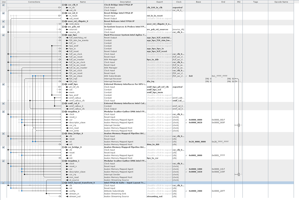
The FPGA AI Suite IP generation utility reads an input Architecture Description File (.arch) and places generated IP into an IP library that can be imported into Platform Designer or used directly in a pure RTL design.
cd $COREDLA_WORK/demo/models/public/resnet-50-tf/FP32

dla_create_ip \
 --flow create_ip \
 --arch=./generated_arch.arch\
 --overwrite \
 --ip_dir ./ip
The newly generated RTL from the create_ip command can be loaded into Quartus® Prime Pro Editionand Platform Designer to see the design and modify or add to the overall design. Quartus® Prime Pro Edition and Platform Designer are not provided as part of FPGA AI Suite and must be obtained separately.