Low Latency Ethernet 10G MAC IP Design Example User Guide: Agilex™ 3 and Agilex™ 5 FPGAs and SoCs
ID
813665
Date
10/24/2025
Public
1. Quick Start Guide
2. 10M/100M/1G/2.5G Ethernet Design Example
3. 10M/100M/1G/2.5G/10G Ethernet Design Example
4. 1G/2.5G Ethernet Design Example with IEEE 1588v2 Feature
5. 1G/2.5G/10G Ethernet Design Example with IEEE 1588v2 Feature
6. 2.5G Ethernet Design Example
7. 2.5G Ethernet Design Example with IEEE 1588v2 Feature
8. 10M/100M/1G/2.5G/10G MGE (Multi Gigabit Ethernet) PCS Only Ethernet Design Example
9. 10M/100M/1G/2.5G/5G/10G (USXGMII) Ethernet Design Example
10. 10M/100M/1G/2.5G/5G/10G (USXGMII) Ethernet Design Example with IEEE 1588v2 Feature
11. Interface Signals Description
12. Configuration Registers Description
13. Low Latency Ethernet 10G MAC IP Design Example User Guide: Agilex™ 3 and Agilex™ 5 FPGAs and SoCs Archives
14. Document Revision History for the Low Latency Ethernet 10G MAC IP Design Example User Guide: Agilex™ 3 and Agilex™ 5 FPGAs and SoCs
8.4. Simulation
The simulation starts up the example design with an operating speed of 10G.
The simulation test case performs the following steps:
- Asserts and deasserts reset to the Dynamic Reconfiguration (DR) controller IP.
- Writes the following to the DR Controller IP registers for profile switching:
- Writes 80030002 to “Register Next ID Configuration 0” to specify the next ID.
- Writes 01 to the “Register Trigger” to trigger the dynamic reconfiguration.
- Waits until dynamic reconfiguration is acknowledged (o_in_progress signal is high).
- Asserts global reset (i_rst_n) to reset the Direct PHY IP.
- Waits for DR Controller IP to be ready (o_in_progress signal is low).
- Waits for reset acknowledgement (o_rst_ack_n signal is low).
- Deasserts the global reset (i_rst_n).
- Configures the MAC and PHY registers.
- Waits until the design example asserts the channel_tx_ready and channel_rx_ready signals.
- Sends the following packets:
- 64-byte packet
- 1518-byte packet
- 100-byte packet
- Repeats steps 2 to 10 for 2.5G and 1G rates.
- Repeat steps 8 to 10 for 100M and 10M speeds.
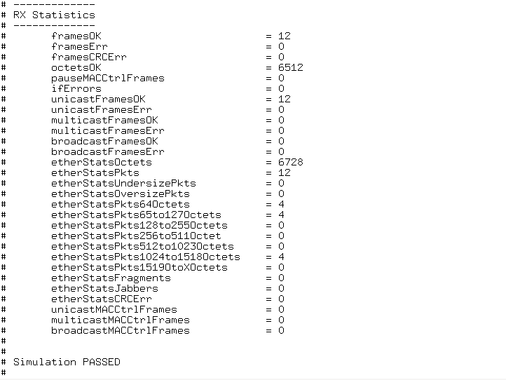
When simulation ends, the values of the MAC statistics counters are displayed in the transcript window. The transcript window also displays PASSED if the RX Avalon® streaming interface of channel 0 received all packets successfully, all statistics error counters are zero, and the RX MAC statistics counters are equal to the TX MAC statistics counters.
Figure 48. Sample Simulation Output