Low Latency Ethernet 10G MAC IP Design Example User Guide: Agilex™ 3 and Agilex™ 5 FPGAs and SoCs
ID
813665
Date
10/24/2025
Public
1. Quick Start Guide
2. 10M/100M/1G/2.5G Ethernet Design Example
3. 10M/100M/1G/2.5G/10G Ethernet Design Example
4. 1G/2.5G Ethernet Design Example with IEEE 1588v2 Feature
5. 1G/2.5G/10G Ethernet Design Example with IEEE 1588v2 Feature
6. 2.5G Ethernet Design Example
7. 2.5G Ethernet Design Example with IEEE 1588v2 Feature
8. 10M/100M/1G/2.5G/10G MGE (Multi Gigabit Ethernet) PCS Only Ethernet Design Example
9. 10M/100M/1G/2.5G/5G/10G (USXGMII) Ethernet Design Example
10. 10M/100M/1G/2.5G/5G/10G (USXGMII) Ethernet Design Example with IEEE 1588v2 Feature
11. Interface Signals Description
12. Configuration Registers Description
13. Low Latency Ethernet 10G MAC IP Design Example User Guide: Agilex™ 3 and Agilex™ 5 FPGAs and SoCs Archives
14. Document Revision History for the Low Latency Ethernet 10G MAC IP Design Example User Guide: Agilex™ 3 and Agilex™ 5 FPGAs and SoCs
2.5.1. Test Procedure
Follow these steps to test the design examples in hardware:
- Click Tools > System Debugging Tools > System Console or run command: system-console &.
- Navigate to the hardware design directory: cd <design_example>/LL10G_1G_2_5G_PHY/hwtesting/system_console.
- Run the following command in the System Console:
source dr_test.tcl
Note: The default DR transition sequence is 2.5G to 1G, then back to 2.5GThe set_jtag command used within hardware tcl file (dr_test.tcl ) places the Agilex™ 5 device on the JTAG chain and the JTAG index is set to 0 by default.
You must connect the external QSFP28 loopback module to bank 1A before running the test.
The example design runs an external loopback test by default, with the loopback_mode parameter set to 0 (parameter.tcl).
- Run the following command in the System Console to trigger the test with dynamic reconfiguration for the supported rates and traffic with Serial Internal Loopback.
- To perform an internal loopback test, you must set the loopback_mode to 1 in the parameter.tcl file, located at <design_example>/ LL10G_1G_2_5G_PHY/hwtesting/system_console:
source dr_test.tcl
- To perform an internal loopback test, you must set the loopback_mode to 1 in the parameter.tcl file, located at <design_example>/ LL10G_1G_2_5G_PHY/hwtesting/system_console:
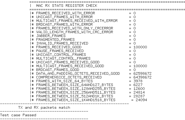
- The following sample output illustrate a successful hardware test run:
Figure 13. Sample Test Output