3. O-RAN IP Functional Description
Mapper
The mapper includes section and common header mapping blocks. The common header consists of a time reference for each packet. The common header format is the same for C-plane and U-plane messages.
C-plane and U-plane messages have the same header format and different transmission time. The IP multiplexes one common header mapper instantiation for mapping both C-plane and U-plane messages. The IP stores information elements (IEs) related to common header and Rtcid ID in a FIFO buffer to bypass section mapper.
Section Mapper
The section format is different for each section type in C-plane and U-plane messages. The IP instantiates a separate control and user mapper to interface with the client. A simple arbiter multiplexes the control and user mapper output for transmission window monitoring and common header mapping.
Dynamic and Static Numerology
You can select Static or Dynamic Numerology. The parameter Enable 30 kHz subcarrier spacing is deprecated, but not removed to ensure compatibility with previous IP versions. For static numerology, set the SCS value before data transfer and do not change the SCS frequency during run time.
For dynamic numerology, set ext_scs_sel to specify the SCS for TX. The C-plane Section Type 3 message specifies the SCS for RX extracted from the framestructure field. The IP processes any SCS value less than 15 kHz as 15kHz SCS according to O-RAN specification 7.2.2.
| 0 (MSB) | 1 | 2 | 3 | 4 | 5 | 6 | 7 (LSB) |
| FFT Size | SCS:
|
||||||
The symbol duration is based on the subcarrier spacing of the packet. The IP adds cyclic prefix duration to the symbol duration calculation to ensure the 14 symbols duration rolls back to 0 every 500 us (non 15 kHz SCS) and 1ms (15kHz SCS). This cyclic prefix duration avoids introducing error rates in each symbol accumulated over the time.
| Numerology (µ) | SCS (kHz) | Symbol Duration (µs) | Slot Duration (µs) |
| 0 | 15 | 66.67 | 1000 |
| 1 | 30 | 33.33 | 500 |
| 2 | 60 | 16.67 | 250 |
| 3 | 120 | 8.33 | 125 |
| 4 | 240 | 4.17 | 62.5 |
The IP bases the numerology for slotId on the highest possible numerology that the IP supports.
For each channel (based on PC_ID), the IP stores the specified SCS value from section type 3 message. Subsequent U-Plane messages to the same channel (PC_ID) use the stored SCS value. The default SCS value is 15k Hz for a channel.
The maximum number of channels for dynamic numerology is 64. Configure the 64 channels by setting the upper six bits of PC_ID
The maximum number of eAxC ID (channels) supported for Dynamic Numerology is 64. You derive these eAxC IDs from sink_rtc_id[15:10] signal through the transport interface for C-plane messages.
For U-plane message, derive the eAxC ID from the sink_pc_id[15:10] signal throgh transport interface for U plane Message
For more information, refer to the O-RAN specification section 7.2.3.3 Slot indexing with mixed numerologies.
RX Path
To set the SCS for a particular eAxC ID, send the type 3 C-plane message. The framestructure field in type3 message contains the information for the SCS.
All the other C-plane message or U-plane message with same eAxC ID follows the SCS set up type3 C-plane message with same eAxC ID
For eAxC ID with no type 3 C-plane message . The SCS defaults to 15 kHz
For invalid SCS values. the SCS defaults to 15 kHz
TX Path
Drive the ext_scs_sel signal tothe following values between SOP and EOP to select the SCS for Dynamic Numerology.
- 4'b0000 for 15 kHz
- 4'b0001 for 30 kHz
- 4'b0010 for 60 kHz
- 4'b0011 for 120 kHz
- 4'b0100 for 240 kHz
For sending Long Prach packets with 1.25 kHz set ext_scs_sel = 4'b1100 and 5 kHz set ext_scs_sel = 4'b1110.
For bypass SRS packets set ext_scs_sel = 4'b1011
By default, the TX SCS for dynamic numerology is set to 15 kHz.
For Invalid values SCS defaults to 15 kHz
Transmission Window
The O-RAN IP transmission window supports the processing of Long PRACH, Short PRACH, SRS, and PUSCH U-plane data packets using the ext_scs_sel application interface input signal.
You should send long PRACH data packets using the SCS channel for 1.25 kHz or 5 kHz frequencies. You should send short PRACH and PUSCH data packets using the standard SCS channel. To bypass the SRS packets from transmission window monitoring, drive the ext_scs_sel signal with the value 4'b1011.
| ext_scs_sel[3:0] | SCS Channel | Window Monitor Registers |
|---|---|---|
| 4'b0000 |
Short PRACH or PUSCH (15 kHz dynamic numerology) | csr_ta3_min_up_ta3_min_up csr_ta3_max_up_ta3_max_up |
| 4'b0001 |
Short PRACH or PUSCH (30 kHz dynamic numerology) | csr_ta3_min_up_ta3_min_up csr_ta3_max_up_ta3_max_up |
| 4'b0010 |
Short PRACH or PUSCH (60 kHz dynamic numerology) |
csr_ta3_min_up_ta3_min_upcsr_ta3_max_up_ta3_max_up |
| 4'b0011 |
Short PRACH or PUSCH (120 kHz dynamic numerology) |
csr_ta3_min_up_ta3_min_upcsr_ta3_max_up_ta3_max_up |
| 4'b0100 | Short PRACH or PUSCH (240 kHz dynamic numerology) |
csr_ta3_min_up_ta3_min_upcsr_ta3_max_up_ta3_max_up |
| 4'b1100 | Long PRACH (1.25 kHz dynamic and static) | csr_ta3_min_up_1p25khz_ta3_min_up_1p25khz, csr_ta3_max_up_1p25khz_ta3_max_up_1p25khz |
| 4'b1110 | Long PRACH (5 kHz dynamic and static) | csr_ta3_min_up_5khz_ta3_min_up_5khz, csr_ta3_max_up_5khz_ta3_max_up_5khz |
| Other | Short PRACH or PUSCH | csr_ta3_min_up_ta3_min_up, csr_ta3_max_up_ta3_max_up |
| 4'b1011 | SRS | The O-RAN IP bypasses SRS packets from transmission window monitor. |
You must perform C-plane and U-plane coupling at the system level outside of O-RAN IP and provide the desired value of ext_scs_sel to apply the SCS frequency accordingly. The IP uses corresponding window monitor registers for each SCS channel transmission window processing.
When sending long PRACH data packets, you must ensure tx_u_symbolid value is 0 for correct air time calculation.
Common Header Mapper
The common header mapper appends the following fields to the start of every packet from the section mapper:
- dataDirection
- payloadVersion
- filterIndex
- frameId
- subframeId
- slotId
- symbolId
This block includes a dispatcher FSM to apply backpressure during insertion of header fields. The block also includes an output FIFO buffer to stream output data with zero or three cycle readyLatency.
Common Header Demapper
The common header demapper demaps the radio application headers from the incoming eCPRI packet and forwards the O-RAN payloads to reception window monitor. This demapper is common for both U-plane and C-plane packets. For every SOP, the IP takes out the MSB nibble and decodes it as a common header. The IP appends the remaining LSB nibble with next clock cycle data and passes it to the next module.
Reception Window Monitoring
The window monitor monitors that the incoming packets fall under current time of day (TOD), if not it drops the current packet. The reception window monitoring shares the same module with the transmission window monitoring. They use different window thresholds, which you program through t2a registers.
Compression and Decompression
A preprocessing block-based bit shift block generates the optimum bit-shifts for a resource block of 12 resource elements (REs). The block reduces the quantization noise, especially for low-amplitude samples. Hence, it reduces the error vector magnitude (EVM) that compression introduces. The compression algorithm is almost independent of the power value. Assuming the complex input samples is x = x1 + jxQ, the maximum absolute value of the real and imaginary components for the resource block is:
The maximum value of the resource block n is:
Having the maximum absolute value for the resource block, the following equation determines the left shift value assigned to that resource block:
Where bitWidth is the input bit width.
The IP supports compression ratios of 8, 9, 10, 11, 12, 13, 14, 15, 16.
For a compression ratio of 16 (udCompParam field = 0, according to the O-RAN WG specification), the IP does not perform compression or decompression.
Mu-Law Compression and Decompression
The algorithm uses Mu-law companding technique, which speech compression widely uses. This technique passes the input uncompressed signal, x, through a compressor with function, f(x), before rounding and bit-truncation. The technique sends compressed data, y, over the interface. The received data passes through an expanding function (which is the inverse of the compressor, F-1(y). The technique reproduces the uncompressed data with minimal quantization error.
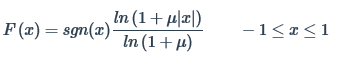
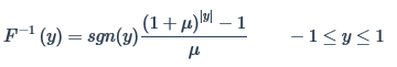
The Mu-law IQ compression algorithm follows the O-RAN specification.
Digital Power Scaling
IQ power level in dB full scale (dBFS) is a logarithmic representation of the power level for an IQ sample carried over the digital interface. IQ power level in dBFS is proportional to logarithm of I²+Q²:
IQ power level [dBFS] = 10·log10( I²+Q² ) - 10·log10(FS)
= 10∙log10 (I²+Q² ) - 10∙log10(FS 0 × 2-FS_Offset )
where:
- I is the in-phase portion of a received constellation point;
- Q is the quadrature portion of a received constellation point;
- FS is the full scale (maximum) permitted value of I or Q based on their digital representations;
- FS_Offset is an M-plane parameter (value 0 if this parameter is not supported by O-RU or not set by O-DU);
- FS 0 = max(I²) = max(Q²) = max(I²+Q²) with max over all IQ values that can be represented by IQ data format in U-plane message.
The actual IQ values that may occur in a U-plane message are restricted by
I²+Q² ≤ FS = FS 0 ×∙ 2(-FS_Offset)
For frequency domain IQ data, 0 dBFS is the maximum power level that one subcarrier can carry over. The smallest non-zero IQ power level is defined by the interface resolution.
O-RU normalizes any received DL value to its internal representation of full scale so that a 0 dBFS can be properly processed.
Example 1:
FS_Offset = 0
I = min I, Q = 0
With 9-bit mantissa 2's complement + 4-bit exponent compression: min I = -256 × 215 = -223
FS 0 = 246, FS = FS 0 2-FS_Offset = 246
0 dBFS is equivalnet to the average(I²+Q²) = 246
Interface resolution is the equivalent to 1/(246), which is the equivalent to -138.47 dBFS
Example 2:
FS_Offset=10
I=min I, Q=0
With 14-bit mantissa 2's complement + 4-bit exponent compression: min I = -213 × 215 = -228, which is the erquivalent to
FS 0 = 256, FS = FS 0 × 2-FS_Offset = 256-10 = 246
0 dBFS is the erquivalent to average(I²+Q²) = 246
Interface resolution is the erquivalent to 1/(246) is the erquivalent to -138.47 dBFS
Digital power scaling is supported for block floating point compression and decompression. You can set the FS Offset values through the IP registers. The FS Offset values can be from 0 to 15. The decompression and compression values are scaled value of square root FS Offset for decompression and compression.
| FS OFFSET | Decompression value | Compression value |
| 0 | 128 | 32,768 |
| 1 | 181 | 23,170 |
| 2 | 256 | 16,384 |
| 3 | 362 | 11,585 |
| 4 | 512 | 8,192 |
| 5 | 724 | 5,792 |
| 6 | 1,024 | 4,096 |
| 7 | 1,448 | 2,896 |
| 8 | 2,048 | 2,048 |
| 9 | 2,896 | 1,448 |
| 10 | 4,096 | 1,024 |
| 11 | ,5793 | 724 |
| 12 | 8,192 | 512 |
| 13 | 11,585 | 362 |
| 14 | 16,384 | 256 |
| 15 | 23,170 | 181 |