P-Tile Avalon® Streaming FPGA IP for PCI Express* User Guide
ID
683059
Date
8/11/2025
Public
1. About the P-tile Avalon® FPGA IPs for PCI Express
2. IP Architecture and Functional Description
3. Advanced Features
4. Interfaces
5. Parameters
6. Testbench
7. Troubleshooting/Debugging
8. P-tile Avalon® Streaming FPGA IP for PCI Express* User Guide Archives
9. Document Revision History for the P-Tile Avalon® Streaming FPGA IP for PCI Express* User Guide
A. Configuration Space Registers
B. Root Port Enumeration
C. Implementation of Address Translation Services (ATS) in Endpoint Mode
D. Packets Forwarded to the User Application in TLP Bypass Mode
E. Using the Avery BFM for Intel P-Tile PCI Express Gen4 x16 Simulations
F. Bifurcated Endpoint Support for Independent Warm Resets
G. Margin Masks for the P-Tile Avalon Streaming FPGA IP for PCI Express
3.2.2.5.1. VirtIO Common Configuration Capability Register (Address: 0x012)
3.2.2.5.2. VirtIO Common Configuration BAR Indicator Register (Address: 0x013)
3.2.2.5.3. VirtIO Common Configuration BAR Offset Register (Address: 0x014)
3.2.2.5.4. VirtIO Common Configuration Structure Length Register (Address 0x015)
3.2.2.5.5. VirtIO Notifications Capability Register (Address: 0x016)
3.2.2.5.6. VirtIO Notifications BAR Indicator Register (Address: 0x017)
3.2.2.5.7. VirtIO Notifications BAR Offset Register (Address: 0x018)
3.2.2.5.8. VirtIO Notifications Structure Length Register (Address: 0x019)
3.2.2.5.9. VirtIO Notifications Notify Off Multiplier Register (Address: 0x01A)
3.2.2.5.10. VirtIO ISR Status Capability Register (Address: 0x02F)
3.2.2.5.11. VirtIO ISR Status BAR Indicator Register (Address: 0x030)
3.2.2.5.12. VirtIO ISR Status BAR Offset Register (Address: 0x031)
3.2.2.5.13. VirtIO ISR Status Structure Length Register (Address: 0x032)
3.2.2.5.14. VirtIO Device Specific Capability Register (Address: 0x033)
3.2.2.5.15. VirtIO Device Specific BAR Indicator Register (Address: 0x034)
3.2.2.5.16. VirtIO Device Specific BAR Offset Register (Address 0x035 )
3.2.2.5.17. VirtIO Device Specific Structure Length Register (Address: 0x036)
3.2.2.5.18. VirtIO PCI Configuration Access Capability Register (Address: 0x037)
3.2.2.5.19. VirtIO PCI Configuration Access BAR Indicator Register (Address: 0x038)
3.2.2.5.20. VirtIO PCI Configuration Access BAR Offset Register (Address: 0x039)
3.2.2.5.21. VirtIO PCI Configuration Access Structure Length Register (Address: 0x03A)
3.2.2.5.22. VirtIO PCI Configuration Access Data Register (Address: 0x03B)
4.1. Overview
4.2. Clocks and Resets
4.3. Serial Data Interface
4.4. Avalon-ST Interface
4.5. Hard IP Status Interface
4.6. Interrupt Interface
4.7. Error Interface
4.8. Hot Plug Interface (RP Only)
4.9. Power Management Interface
4.10. Configuration Output Interface
4.11. Configuration Intercept Interface (EP Only)
4.12. Hard IP Reconfiguration Interface
4.13. PHY Reconfiguration Interface
4.14. Page Request Service (PRS) Interface (EP Only)
4.4.1. TLP Header and Data Alignment for the Avalon-ST RX and TX Interfaces
4.4.2. Avalon® -ST RX Interface
4.4.3. Avalon® -ST RX Interface rx_st_ready Behavior
4.4.4. RX Flow Control Interface
4.4.5. Avalon® -ST TX Interface
4.4.6. Avalon® -ST TX Interface tx_st_ready Behavior
4.4.7. TX Flow Control Interface
4.4.8. Tag Allocation
5.2.3.1. Device Capabilities
5.2.3.2. VirtIO Parameters
5.2.3.3. Link Capabilities
5.2.3.4. Legacy Interrupt Pin Register
5.2.3.5. MSI Capabilities
5.2.3.6. MSI-X Capabilities
5.2.3.7. Slot Capabilities
5.2.3.8. Latency Tolerance Reporting (LTR)
5.2.3.9. Process Address Space ID (PASID)
5.2.3.10. Device Serial Number Capability
5.2.3.11. Page Request Service (PRS)
5.2.3.12. Access Control Service (ACS) Capabilities
5.2.3.13. Power Management
5.2.3.14. Vendor Specific Extended Capability (VSEC) Registers
5.2.3.15. TLP Processing Hints (TPH)
5.2.3.16. Address Translation Services (ATS) Capabilities
6.3.5.1. ebfm_barwr Procedure
6.3.5.2. ebfm_barwr_imm Procedure
6.3.5.3. ebfm_barrd_wait Procedure
6.3.5.4. ebfm_barrd_nowt Procedure
6.3.5.5. ebfm_cfgwr_imm_wait Procedure
6.3.5.6. ebfm_cfgwr_imm_nowt Procedure
6.3.5.7. ebfm_cfgrd_wait Procedure
6.3.5.8. ebfm_cfgrd_nowt Procedure
6.3.5.9. BFM Configuration Procedures
6.3.5.10. BFM Shared Memory Access Procedures
6.3.5.11. BFM Log and Message Procedures
6.3.5.12. Verilog HDL Formatting Functions
6.3.5.11.1. ebfm_display Verilog HDL Function
6.3.5.11.2. ebfm_log_stop_sim Verilog HDL Function
6.3.5.11.3. ebfm_log_set_suppressed_msg_mask Task
6.3.5.11.4. ebfm_log_set_stop_on_msg_mask Verilog HDL Task
6.3.5.11.5. ebfm_log_open Verilog HDL Function
6.3.5.11.6. ebfm_log_close Verilog HDL Function
A.3.1. Intel-Defined VSEC Capability Header (Offset 00h)
A.3.2. Intel-Defined Vendor Specific Header (Offset 04h)
A.3.3. Intel Marker (Offset 08h)
A.3.4. JTAG Silicon ID (Offset 0x0C - 0x18)
A.3.5. User Configurable Device and Board ID (Offset 0x1C - 0x1D)
A.3.6. General Purpose Control and Status Register (Offset 0x30)
A.3.7. Uncorrectable Internal Error Status Register (Offset 0x34)
A.3.8. Uncorrectable Internal Error Mask Register (Offset 0x38)
A.3.9. Correctable Internal Error Status Register (Offset 0x3C)
A.3.10. Correctable Internal Error Mask Register (Offset 0x40)
5.2.3.2. VirtIO Parameters
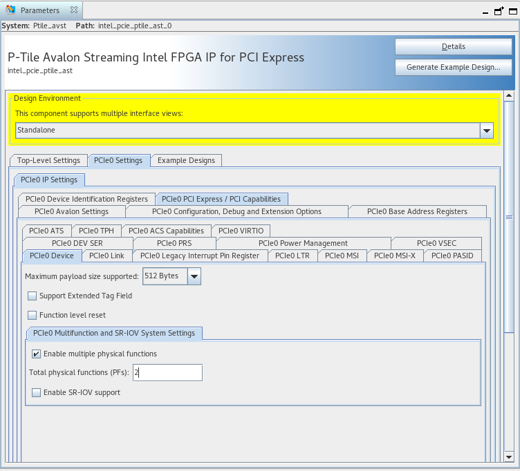
To enable VirtIO support, first enable the support for multiple physical functions in the IP Parameter Editor as shown in the following screenshot:
Figure 57. Enable Multifunction Support
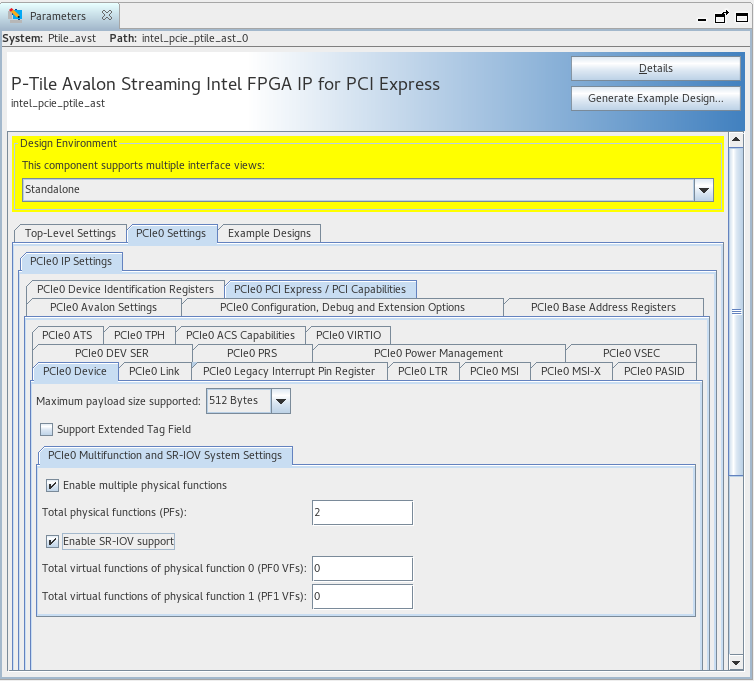
Make sure that SR-IOV support is also enabled:
Figure 58. Enable SR-IOV Support
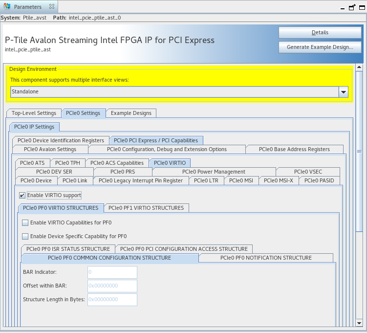
Enable VirtIO support as shown in the screenshot below:
Figure 59. Enable VirtIO Support
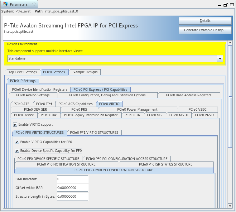
Finally, you can configure the appropriate VirtIO capability parameters in the tabs shown in the screenshot below:
Figure 60. Configure VirtIO Capability Parameters
The following table provides a reference for all the configurable high-level parameters of the VirtIO block for P-Tile. Parameters below are dedicated to each core.
| Parameter | Description | Allowed Range | Default Value |
|---|---|---|---|
| Enable PF VirtIO | Enable Physical Function 0-7 VirtIO capability. | True/False | False |
| Enable VF VirtIO | Enable VirtIO capability of VFs associated with PFs 0-7. | True/False | False |
The next table summarizes the parameters associated with the five VirtIO device configuration structures:
| Parameter | Description | Allowed Range | Default Value |
|---|---|---|---|
| PF/VF VirtIO Common Configuration Structure Capability Parameters | |||
| PFs 0-7 Common Configuration Structure BAR Indicator | Indicates BAR holding the Common Configuration Structure of PFs 0-7. | 0-5 | 0 |
| PFs 0-7 VFs Common Configuration Structure BAR Indicator | Indicates BAR holding the Common Configuration Structure of VFs associated with PFs 0-7. | 0-5 | 0 |
| PFs 0-7 Common Configuration Structure Offset within BAR | Indicates starting position of Common Config Structure in a given BAR of PFs 0-7. | 0-536870911 | 0 |
| PFs 0-7 VFs Common Configuration Structure BAR Indicator | Indicates starting position of Common Config Structure in a given BAR of VFs associated with PFs 0-7. | 0-536870911 | 0 |
| PFs 0-7 Common Configuration Structure Length | Indicates length in bytes of Common Config Structure of PFs 0-7. | 0-536870911 | 0 |
| PFs 0-7 VFs Common Configuration Structure Length | Indicates length in bytes of Common Config Structure of VFs associated with PFs 0-7. | 0-536870911 | 0 |
| PF/VF VirtIO Notifications Structure Capability Parameters | |||
| PFs 0-7 Notifications Structure BAR Indicator | Indicates BAR holding the Notifications Structure of PFs 0-7. | 0-5 | 0 |
| PFs 0-7 VFs Notifications Structure BAR Indicator | Indicates BAR holding the Notifications Structure of VFs associated with PFs 0-7. | 0-5 | 0 |
| PFs 0-7 Notifications Structure Offset within BAR | Indicates starting position of Notifications Structure in given BAR of PFs 0-7. | 0-536870911 | 0 |
| PFs 0-7 VFs Notifications Structure BAR Indicator | Indicates starting position of Notifications Structure in given BAR of VFs associated with PFs 0-7. | 0-536870911 | 0 |
| PFs 0-7 Notifications Structure Length | Indicates length in bytes of Notifications Structure of PFs 0-7. | 0-536870911 | 0 |
| PFs 0-7 VFs Notifications Structure Length | Indicates length in bytes of Notifications Structure of VFs associated with PFs 0-7. | 0-536870911 | 0 |
| PFs 0-7 Notifications Structure Notify Off Multiplier | Indicates multiplier for queue_notify_off in Notifications Structure of PFs 0-7. | 0-536870911 | 0 |
| PFs 0-7 VFs Notifications Structure Notify Off Multiplier | Indicates multiplier for queue_notify_off in Notifications Structure of VFs associated with PFs 0-7. | 0-536870911 | 0 |
| PF/VF VirtIO ISR Status Structure Capability Parameters | |||
| PFs 0-7 ISR Status Structure BAR Indicator | Indicates BAR holding the ISR Status Structure of PFs 0-7. | 0-5 | 0 |
| PFs 0-7 VFs ISR Status Structure BAR Indicator | Indicates BAR holding the ISR Status Structure of VFs associated with PFs 0-7. | 0-5 | 0 |
| PFs 0-7 ISR Status Structure Offset within BAR | Indicates starting position of ISR Status Structure in given BAR of PFs 0-7. | 0-536870911 | 0 |
| PFs 0-7 VFs ISR Status Structure BAR Indicator | Indicates starting position of ISR Status Structure in given BAR of VFs associated with PFs 0-7. | 0-536870911 | 0 |
| PFs 0-7 ISR Status Structure Length | Indicates length in bytes of ISR Status Structure of PFs 0-7. | 0-536870911 | 0 |
| PFs 0-7 VFs ISR Status Structure Length | Indicates length in bytes of ISR Status Structure of VFs associated with PFs 0-7. | 0-536870911 | 0 |
| PF/VF VirtIO Device-Specific Configuration Structure Capability Parameters | |||
| Enable PFs 0-7 VirtIO Device Specific Capability | Enable PFs 0-7 VirtIO Device-Specific Configuration Structure Capability. | True / False | False |
| Enable PFs 0-7 VFs VirtIO Device-Specific Capability | Enable VirtIO Device-Specific Configuration Structure Capability of VFs associated with PFs 0-7. | True / False | False |
| PFs 0-7 Device-Specific Configuration Structure BAR Indicator | Indicates BAR holding the Device-Specific Configuration Structure of PFs 0-7. |
0-5 | 0 |
| PFs 0-7 VFs Device-Specific Configuration Structure BAR Indicator | Indicates BAR holding the Device-Specific Configuration Structure of VFs associated with PFs 0-7. | 0-5 | 0 |
| PFs 0-7 Device-Specific Configuration Structure Offset within BAR | Indicates starting position of Device-Specific Configuration Structure in given BAR of PFs 0-7. | 0-536870911 | 0 |
| PFs 0-7 VFs Device-Specific Configuration Structure BAR Indicator | Indicates starting position of Device-Specific Configuration Structure in given BAR of VFs associated with PFs 0-7. | 0-536870911 | 0 |
| PFs 0-7 Device-Specific Configuration Structure Length | Indicates length in bytes of Device-Specific Configuration Structure of PFs 0-7. | 0-536870911 | 0 |
| PFs 0-7 VFs Device-Specific Configuration Structure Length | Indicates length in bytes of Device-Specific Configuration Structure of VFs associated with PFs 0-7. | 0-536870911 | 0 |