View PDF [736 KB]
Back to: Part 5 Staging Resources
Next up: Uniform Buffers - Using Buffers in Shaders
Tutorial 6: Descriptor Sets – Using Textures in Shaders
We know how to create a graphics pipeline and how to use shaders to draw geometry on screen. We have also learned how to create buffers and use them as a source of vertex data (vertex buffers). Now we need to know how to provide data to shaders—we will see how to use resources like samplers and images inside shader source code and how to set up an interface between the application and the programmable shader stages.
In this tutorial, we will focus on a functionality that is similar to OpenGL* textures. But in Vulkan* there are no such objects. We have only two resource types in which we can store data: buffers and images (there are also push constants, but we will cover them in a dedicated tutorial). Each of them can be provided to shaders, in which case we call such resources descriptors, but we can’t provide them to shaders directly. Instead, they are aggregated in wrapper or container objects called descriptor sets. We can place multiple resources in a single descriptor set but we need to do it according to a predefined structure of such set. This structure defines the contents of a single descriptor set—types of resources that are placed inside it, number of each of these resource types, and their order. This description is specified inside objects named descriptor set layouts. Similar descriptions need to be specified when we write shader programs. Together they form an interface between API (our application) and the programmable pipeline (shaders).
When we have prepared a layout, and created a descriptor set, we can fill it; in this way we define specific objects (buffers and/or images) that we want to use in shaders. After that, before issuing drawing commands inside a command buffer, we need to bind such a set to the command buffer. This allows us to use the resources from inside the shader source code; for example, fetch data from a sampled image (a texture), or read a value of a uniform variable stored in a uniform buffer.
In this part of the tutorial, we will see how to create descriptor set layouts and descriptor sets themselves. We will also prepare a sampler and an image so we can make them available as a texture inside shaders. We will also learn how we can use them inside shaders.
As mentioned previously, this tutorial is based on the knowledge presented in all the previous parts of the API without Secrets: Introduction to Vulkan tutorials, and only the differences and parts important for the described topics are presented.
Creating an Image
We start by creating an image that will act as our texture. Images represent a continuous area of memory, which is interpreted according to the rules defined during image creation. In Vulkan, we have only three basic image types: 1D, 2D, and 3D. Images may have mipmaps (levels of detail), many array layers (at least one is required), or samples per frame. All these parameters are specified during image creation. In the code sample, we create the most commonly used two‑dimensional image, with one sample per pixel and the four RGBA components.
VkImageCreateInfo image_create_info = {
  VK_STRUCTURE_TYPE_IMAGE_CREATE_INFO,  // VkStructureType        sType;
  nullptr,                              // const void            *pNext
  0,                                    // VkImageCreateFlags     flags
  VK_IMAGE_TYPE_2D,                     // VkImageType            imageType
  VK_FORMAT_R8G8B8A8_UNORM,             // VkFormat               format
  {                                     // VkExtent3D             extent
    width,                                // uint32_t               width
    height,                               // uint32_t               height
    1                                     // uint32_t               depth
  },
  1,                                    // uint32_t               mipLevels
  1,                                    // uint32_t               arrayLayers
  VK_SAMPLE_COUNT_1_BIT,                // VkSampleCountFlagBits  samples
  VK_IMAGE_TILING_OPTIMAL,              // VkImageTiling          tiling
  VK_IMAGE_USAGE_TRANSFER_DST_BIT |     // VkImageUsageFlags      usage
  VK_IMAGE_USAGE_SAMPLED_BIT,
  VK_SHARING_MODE_EXCLUSIVE,            // VkSharingMode          sharingMode
  0,                                    // uint32_t               queueFamilyIndexCount
  nullptr,                              // const uint32_t        *pQueueFamilyIndices
  VK_IMAGE_LAYOUT_UNDEFINED             // VkImageLayout          initialLayout
};

return vkCreateImage( GetDevice(), &image_create_info, nullptr, image ) == VK_SUCCESS;
1.Tutorial06.cpp, function CreateImage()
To create an image we need to prepare a structure of type VkImageCreateInfo. This structure contains the basic set of parameters required to create an image. These parameters are specified through the following members:
- sType – Typical type of the structure. It must be equal to a VK_STRUCTURE_TYPE_IMAGE_CREATE_INFO value.
- pNext – Pointer reserved for extensions.
- flags–Parameter that describes additional properties of an image. Through this parameter we can specify that the image can be backed by a sparse memory. But a more interesting value is a VK_IMAGE_CREATE_CUBE_COMPATIBLE_BIT, which allows us to use the image as a cubemap. If we don’t have additional requirements, we can set this parameter to 0.
- imageType – Basic type (number of dimensions) of the image: 1D, 2D, or 3D.
- format – Format of the image: number of its components, number of bits for each component, and a data type.
- extent – Size of the image (number of texels/pixels) in each dimension.
- mipLevels – Number of levels of detail (mipmaps).
- arrayLayers – Number of array layers.
- samples – Number of per texel samples (one for normal images and more than one for multisampled images).
- tiling – Defines the inner memory structure of the image: linear or optimal.
- usage – Defines all the ways in which we want to use an image during its overall lifetime.
- sharingMode – Specifies whether an image will be accessed by queues from multiple families at a time (the same as the sharingMode parameter used during swapchain or buffer creation).
- queueFamilyIndexCount–Number of elements in a pQueueFamilyIndices array (used only when concurrent sharing mode is specified).
- pQueueFamilyIndices – Array with indices of all queue families from which queues will access an image (used only when concurrent sharing mode is specified).
- initialLayout – Memory layout image will be created with. We can only provide an undefined or preinitialized layout. We also need to perform a layout transition before we can use an image inside command buffers.
Most of the parameters defined during image creation are quite self-explanatory or similar to parameters used during creation of other resources. But three parameters require additional explanation.
Tiling defines the inner memory structure of an image (but don’t confuse it with a layout). Images may have linear or optimal tiling (buffers always have linear tiling). Images with linear tiling have their texels laid out linearly, one texel after another, one row after another, and so on. We can query for all the relevant image’s memory parameters (offset and size, row, array, and depth stride). This way we know how the image’s contents are kept in memory. Such tiling can be used to copy data to an image directly (by mapping the image’s memory). Unfortunately, there are severe restrictions on images with linear tiling. For example, the Vulkan specification says that only 2D images must support linear tiling. Hardware vendors may implement support for linear tiling in other image types, but this is not obligatory, and we can’t rely on such support. But, what’s more important, linearly tiled images may have worse performance than their optimal counterparts.
When we specify an optimal tiling for images, it means that we don’t know how their memory is structured. Each platform we execute our application on may keep an image’s contents in a totally different way, so it’s practically impossible to map an image’s memory and copy it to or from the CPU directly (we need to use a staging resource, a buffer or an image). But this way we can create whatever images we want (there are no restrictions similar to linearly tiled images) and our application will have better performance. That’s why it is strongly suggested to always specify optimal tiling for images.
Now let’s focus on an initialLayout parameter. Layout, as it was described in a tutorial about swapchains, defines an image’s memory layout and is strictly connected with the way in which we want to use an image. Each specific usage has its own memory layout. Before we can use an image in a given way we need to perform a layout transition. For example, swapchain images can be displayed on screen only in VK_IMAGE_LAYOUT_PRESENT_SRC_KHR layout. When we want to render into an image, we need to set its memory layout to VK_IMAGE_LAYOUT_COLOR_ATTACHMENT_OPTIMAL. There is also a general layout that allows us to use images any way we want to, but as it impacts performance, it’s use is strongly discouraged (use only when really necessary).
Now, when we want to change the way in which an image is used, we need to perform the above-mentioned layout transition. We must specify a current (old) layout and a new one. The old layout can have one of two values: current image layout or an undefined layout. When we specify the value of a current image’s layout, the image contents are preserved during transition. But when we don’t need an image’s contents, we can provide an undefined layout. In this way layout transition may be performed faster.
And this is when the initialLayout parameter comes in. We can specify only two values for it—undefined or preinitialized. The preinitialized layout value allows us to preserve an image’s contents during the image’s first layout transition. This way we can copy data to an image with memory mapping; but this is quite impractical. We can only copy data directly (through memory mapping) to images with linear tiling, which have restrictions as mentioned above. Practically speaking, these images can only be used as staging resources—for transferring data between GPU and CPU. But for this purpose we can also use buffers; that’s why it is much easier to copy data using a buffer than using an image with linear tiling.
All this leads to the conclusion that, in most cases, an undefined layout can be used for an initialLayout parameter. In such a case, an image’s contents cannot be initialized directly (by mapping its memory). But if we want to, we can copy data to such an image by using a staging buffer. That approach is presented in this tutorial.
One last thing we need to remember is the usage. Similar to buffers, when we create an image we need to designate ALL the ways in which we intend to use the image. We can’t change it later and we can’t use the image in a way that wasn’t specified during its creation. Here, we want to use an image as a texture inside shaders. For this purpose we specify the VK_IMAGE_USAGE_SAMPLED_BIT usage. We also need a way to upload data to the image. We are going to read it from an image file and copy it to the image object. This can be done by transferring data using a staging resource. In such a case, the image will be a target of a transfer operation; that’s why we also specify the VK_IMAGE_USAGE_TRANSFER_DST_BIT usage.
Now, when we have provided values for all the parameters, we can create an image. This is done by calling the vkCreateImage() function for which we need to provide a handle of a logical device, a pointer to the structure described above, and a pointer to a variable of type VkImage in which the handle of the created image will be stored.
Allocating Image Memory
Similar to buffers, images don’t have their own memory, so before we can use images we need to bind memory to them. To do this, we first need to know what the properties of memory that can be bound to an image are. We do this by calling the vkGetImageMemoryRequirements() function.
VkMemoryRequirements image_memory_requirements;
vkGetImageMemoryRequirements( GetDevice(), Vulkan.Image.Handle, &image_memory_requirements );
2.Tutorial06.cpp, function AllocateImageMemory()
The above call stores the required memory parameters in an image_memory_requirements variable. This tells us how much memory we need and which memory type supported by a given physical device can be used for an image’s memory allocation. If we don’t know what memory types are supported by a given physical device we can learn about them by calling the vkGetPhysicalDeviceMemoryProperties() function. This was covered in a previous tutorial, when we were allocating memory for a buffer. Next, we can iterate over available memory types and check which are compatible with our image.
for( uint32_t i = 0; i < memory_properties.memoryTypeCount; ++i ) {
  if( (image_memory_requirements.memoryTypeBits & (1 << i)) &&
    (memory_properties.memoryTypes[i].propertyFlags & property) ) {

    VkMemoryAllocateInfo memory_allocate_info = {
      VK_STRUCTURE_TYPE_MEMORY_ALLOCATE_INFO, // VkStructureType  sType
      nullptr,                                // const void      *pNext
      image_memory_requirements.size,         // VkDeviceSize     allocationSize
      i                                       // uint32_t         memoryTypeIndex
    };

    if( vkAllocateMemory( GetDevice(), &memory_allocate_info, nullptr, memory ) == VK_SUCCESS ) {
      return true;
    }
  }
}
return false;
3.Tutorial06.cpp, function AllocateImageMemory()
Each memory type has a specific set of properties. When we want to bind memory to an image, we can have our own specific requirements too. For example, we may need to access memory directly, by mapping it, so such memory must be host-visible. If we have additional requirements we can compare them with the properties of each available memory type. When we find the match, we can use a given memory type and allocate a memory object from it by calling the vkAllocateMemory() function.
After that, we need to bind such memory to our image. We do this by calling the vkBindImageMemory() function and providing the handle of an image to which we want to bind memory, a handle of a memory object, and an offset from the beginning of the memory object, like this:
if( vkBindImageMemory( GetDevice(), Vulkan.Image.Handle, Vulkan.Image.Memory, 0 ) != VK_SUCCESS ) {
  std::cout << "Could not bind memory to an image!" << std::endl;
  return false;
}
4.Tutorial06.cpp, function CreateTexture()
Offset value is very important when we bind memory to an object. Resources in Vulkan have specific requirements for memory offset alignment. Information about the requirements is also available in the image_memory_requirements variable. The offset that we provide when we bind a memory must be a multiple of the variable’s alignment member. Zero is always a valid offset value.
Of course, when we want to bind a memory to an image, we don’t need to create a new memory object each time. It is more optimal to create a small number of larger memory objects and bind parts of them by providing a proper offset value.
Creating Image View
When we want to use an image in our application we rarely provide the image’s handle. Image views are usually used instead. They provide an additional layer that interprets the contents of an image for the purpose of using it in a specific context. For example, we may have a multilayer image (2D array) and we want to render only to a specific array layer. To do this we create an image view in which we define the layer we want to use. Another example is an image with six array layers. Using image views, we can interpret it as a cubemap.
Creation of image views was described in Introduction to Vulkan Part 3: First Triangle, so I will provide only the source code used in this part.
VkImageViewCreateInfo image_view_create_info = {
  VK_STRUCTURE_TYPE_IMAGE_VIEW_CREATE_INFO, // VkStructureType          sType
  nullptr,                                  // const void              *pNext
  0,                                        // VkImageViewCreateFlags   flags
  image_parameters.Handle,                  // VkImage                  image
  VK_IMAGE_VIEW_TYPE_2D,                    // VkImageViewType          viewType
  VK_FORMAT_R8G8B8A8_UNORM,                 // VkFormat                 format
  {                                         // VkComponentMapping       components
    VK_COMPONENT_SWIZZLE_IDENTITY,            // VkComponentSwizzle       r
    VK_COMPONENT_SWIZZLE_IDENTITY,            // VkComponentSwizzle       g
    VK_COMPONENT_SWIZZLE_IDENTITY,            // VkComponentSwizzle       b
    VK_COMPONENT_SWIZZLE_IDENTITY             // VkComponentSwizzle       a
  },
  {                                         // VkImageSubresourceRange  subresourceRange
    VK_IMAGE_ASPECT_COLOR_BIT,                // VkImageAspectFlags       aspectMask
    0,                                        // uint32_t                 baseMipLevel
    1,                                        // uint32_t                 levelCount
    0,                                        // uint32_t                 baseArrayLayer
    1                                         // uint32_t                 layerCount
  }
};

return vkCreateImageView( GetDevice(), &image_view_create_info, nullptr, &image_parameters.View ) == VK_SUCCESS;
5.Tutorial06.cpp, function CreateImageView()
Copying Data to an Image
Now we need to copy data to our image. We do this by using a staging buffer. We first create a buffer big enough to hold our image data. Next, we allocate memory that is host-visible (that can be mapped), and bind it to the buffer. Then, we copy data to the buffer’s memory like this:
// Prepare data in staging buffer
void *staging_buffer_memory_pointer;
if( vkMapMemory( GetDevice(), Vulkan.StagingBuffer.Memory, 0, data_size, 0, &staging_buffer_memory_pointer ) != VK_SUCCESS ) {
  std::cout << "Could not map memory and upload texture data to a staging buffer!" << std::endl;
  return false;
}

memcpy( staging_buffer_memory_pointer, texture_data, data_size );

VkMappedMemoryRange flush_range = {
  VK_STRUCTURE_TYPE_MAPPED_MEMORY_RANGE,  // VkStructureType   sType
  nullptr,                                // const void       *pNext
  Vulkan.StagingBuffer.Memory,            // VkDeviceMemory    memory
  0,                                      // VkDeviceSize      offset
  data_size                               // VkDeviceSize      size
};
vkFlushMappedMemoryRanges( GetDevice(), 1, &flush_range );

vkUnmapMemory( GetDevice(), Vulkan.StagingBuffer.Memory );
6.Tutorial06.cpp, function CopyTextureData()
We map the buffer’s memory. This operation gives us a pointer that can be used the way that all other C++ pointers are used. We copy texture data to it and inform the driver which parts of the buffer’s memory were changed during this operation (we flush the memory). At the end, we unmap the memory, but this is not necessary.
Image data is read from a file with the following code:
int width = 0, height = 0, data_size = 0;
std::vector texture_data = Tools::GetImageData( "Data06/texture.png", 4, &width, &height, nullptr, &data_size );
if( texture_data.size() == 0 ) {
  return false;
}

if( !CopyTextureData( &texture_data[0], data_size, width, height ) ) {
  std::cout << "Could not upload texture data to device memory!" << std::endl;
  return false;
}
7.Tutorial06.cpp, function CreateTexture()
For the purpose of this tutorial we will use the following image as a texture:

The operation of copying data from a buffer to an image requires recording a command buffer and submitting it to a queue. Calling the vkBeginCommandBuffer() function starts the recording operation:
// Prepare command buffer to copy data from staging buffer to a vertex buffer
VkCommandBufferBeginInfo command_buffer_begin_info = {
  VK_STRUCTURE_TYPE_COMMAND_BUFFER_BEGIN_INFO,  // VkStructureType                        sType
  nullptr,                                      // const void                            *pNext
  VK_COMMAND_BUFFER_USAGE_ONE_TIME_SUBMIT_BIT,  // VkCommandBufferUsageFlags              flags
  nullptr                                       // const VkCommandBufferInheritanceInfo  *pInheritanceInfo
};

VkCommandBuffer command_buffer = Vulkan.RenderingResources[0].CommandBuffer;

vkBeginCommandBuffer( command_buffer, &command_buffer_begin_info);
8.Tutorial06.cpp, function CopyTextureData()
At the beginning of the command buffer recording we need to perform a layout transition on our image. We want to copy data to the image so we need to change its layout to a VK_IMAGE_LAYOUT_TRANSFER_DST_OPTIMAL. We need to do this explicitly using an image memory barrier and calling the vkCmdPipelineBarrier() function:
VkImageSubresourceRange image_subresource_range = {
  VK_IMAGE_ASPECT_COLOR_BIT,              // VkImageAspectFlags        aspectMask
  0,                                      // uint32_t                  baseMipLevel
  1,                                      // uint32_t                  levelCount
  0,                                      // uint32_t                  baseArrayLayer
  1                                       // uint32_t                  layerCount
};

VkImageMemoryBarrier image_memory_barrier_from_undefined_to_transfer_dst = {
  VK_STRUCTURE_TYPE_IMAGE_MEMORY_BARRIER, // VkStructureType           sType
  nullptr,                                // const void               *pNext
  0,                                      // VkAccessFlags             srcAccessMask
  VK_ACCESS_TRANSFER_WRITE_BIT,           // VkAccessFlags             dstAccessMask
  VK_IMAGE_LAYOUT_UNDEFINED,              // VkImageLayout             oldLayout
  VK_IMAGE_LAYOUT_TRANSFER_DST_OPTIMAL,   // VkImageLayout             newLayout
  VK_QUEUE_FAMILY_IGNORED,                // uint32_t                  srcQueueFamilyIndex
  VK_QUEUE_FAMILY_IGNORED,                // uint32_t                  dstQueueFamilyIndex
  Vulkan.Image.Handle,                    // VkImage                   image
  image_subresource_range                 // VkImageSubresourceRange   subresourceRange
};
vkCmdPipelineBarrier( command_buffer, VK_PIPELINE_STAGE_TOP_OF_PIPE_BIT, VK_PIPELINE_STAGE_TRANSFER_BIT, 0, 0, nullptr, 0, nullptr, 1, &image_memory_barrier_from_undefined_to_transfer_dst);
9.Tutorial06.cpp, function CopyTextureData()
Next, we can copy the data itself. To do this we need to provide parameters describing both a source and a destination for the data: which parts of the image we want to update (imageSubresource member), a specific region within the provided part (imageOffset), and the total size of the image. For the source of the data we need to provide an offset from the beginning of a buffer’s memory where the data starts, and how this data is structured, and the size of an imaginary image inside the buffer (the size of its rows and columns). Fortunately, we can store our data in such a way that it fits our image. This allows us to set a zero value for both parameters (bufferRowLength and bufferImageHeight), specifying that the data is tightly packed according to the image size.
VkBufferImageCopy buffer_image_copy_info = {
  0,                                  // VkDeviceSize               bufferOffset
  0,                                  // uint32_t                   bufferRowLength
  0,                                  // uint32_t                   bufferImageHeight
  {                                   // VkImageSubresourceLayers   imageSubresource
    VK_IMAGE_ASPECT_COLOR_BIT,          // VkImageAspectFlags         aspectMask
    0,                                  // uint32_t                   mipLevel
    0,                                  // uint32_t                   baseArrayLayer
    1                                   // uint32_t                   layerCount
  },
  {                                   // VkOffset3D                 imageOffset
    0,                                  // int32_t                    x
    0,                                  // int32_t                    y
    0                                   // int32_t                    z
  },
  {                                   // VkExtent3D                 imageExtent
    width,                              // uint32_t                   width
    height,                             // uint32_t                   height
    1                                   // uint32_t                   depth
  }
};
vkCmdCopyBufferToImage( command_buffer, Vulkan.StagingBuffer.Handle, Vulkan.Image.Handle, VK_IMAGE_LAYOUT_TRANSFER_DST_OPTIMAL, 1, &buffer_image_copy_info );
10.Tutorial06.cpp, function CopyTextureData()
One last thing is to perform another layout transition. Our image will be used as a texture inside shaders, so we need to transition it to a VK_IMAGE_LAYOUT_SHADER_READ_ONLY_OPTIMAL layout. After that, we can end our command buffer, submit it to a queue, and wait for the transfer to complete (in a real-life application, we should skip waiting and synchronize operations in some other way; for example, using semaphores, to avoid unnecessary pipeline stalls).
VkImageMemoryBarrier image_memory_barrier_from_transfer_to_shader_read = {
  VK_STRUCTURE_TYPE_IMAGE_MEMORY_BARRIER,   // VkStructureType              sType
  nullptr,                                  // const void                  *pNext
  VK_ACCESS_TRANSFER_WRITE_BIT,             // VkAccessFlags                srcAccessMask
  VK_ACCESS_SHADER_READ_BIT,                // VkAccessFlags                dstAccessMask
  VK_IMAGE_LAYOUT_TRANSFER_DST_OPTIMAL,     // VkImageLayout                oldLayout
  VK_IMAGE_LAYOUT_SHADER_READ_ONLY_OPTIMAL, // VkImageLayout                newLayout
  VK_QUEUE_FAMILY_IGNORED,                  // uint32_t                     srcQueueFamilyIndex
  VK_QUEUE_FAMILY_IGNORED,                  // uint32_t                     dstQueueFamilyIndex
  Vulkan.Image.Handle,                      // VkImage                      image
  image_subresource_range                   // VkImageSubresourceRange      subresourceRange
};
vkCmdPipelineBarrier( command_buffer, VK_PIPELINE_STAGE_TRANSFER_BIT, VK_PIPELINE_STAGE_FRAGMENT_SHADER_BIT, 0, 0, nullptr, 0, nullptr, 1, &image_memory_barrier_from_transfer_to_shader_read);

vkEndCommandBuffer( command_buffer );

// Submit command buffer and copy data from staging buffer to a vertex buffer
VkSubmitInfo submit_info = {
  VK_STRUCTURE_TYPE_SUBMIT_INFO,            // VkStructureType              sType
  nullptr,                                  // const void                  *pNext
  0,                                        // uint32_t                     waitSemaphoreCount
  nullptr,                                  // const VkSemaphore           *pWaitSemaphores
  nullptr,                                  // const VkPipelineStageFlags  *pWaitDstStageMask;
  1,                                        // uint32_t                     commandBufferCount
  &command_buffer,                          // const VkCommandBuffer       *pCommandBuffers
  0,                                        // uint32_t                     signalSemaphoreCount
  nullptr                                   // const VkSemaphore           *pSignalSemaphores
};

if( vkQueueSubmit( GetGraphicsQueue().Handle, 1, &submit_info, VK_NULL_HANDLE ) != VK_SUCCESS ) {
  return false;
}

vkDeviceWaitIdle( GetDevice() );
11.Tutorial06.cpp, function CopyTextureData()
Now our image is created and fully initialized (contains proper data). But we are not yet done preparing our texture.
Creating a Sampler
In OpenGL, when we created a texture, both the image and its sampling parameters had to be specified. In later versions of OpenGL we could also create separate sampler objects. Inside a shader, we usually created variables of type sampler2D, which also combined both images and their sampling parameters (samplers). In Vulkan, we need to create images and samplers separately.
Samplers define the way in which image data is read inside shaders: whether filtering is enabled, whether we want to use mipmaps (or maybe a specific subrange of mipmaps), or what kind of addressing mode we want to use (clamping or wrapping).
VkSamplerCreateInfo sampler_create_info = {
  VK_STRUCTURE_TYPE_SAMPLER_CREATE_INFO,  // VkStructureType        sType
  nullptr,                                // const void*            pNext
  0,                                      // VkSamplerCreateFlags   flags
  VK_FILTER_LINEAR,                       // VkFilter               magFilter
  VK_FILTER_LINEAR,                       // VkFilter               minFilter
  VK_SAMPLER_MIPMAP_MODE_NEAREST,         // VkSamplerMipmapMode    mipmapMode
  VK_SAMPLER_ADDRESS_MODE_CLAMP_TO_EDGE,  // VkSamplerAddressMode   addressModeU
  VK_SAMPLER_ADDRESS_MODE_CLAMP_TO_EDGE,  // VkSamplerAddressMode   addressModeV
  VK_SAMPLER_ADDRESS_MODE_CLAMP_TO_EDGE,  // VkSamplerAddressMode   addressModeW
  0.0f,                                   // float                  mipLodBias
  VK_FALSE,                               // VkBool32               anisotropyEnable
  1.0f,                                   // float                  maxAnisotropy
  VK_FALSE,                               // VkBool32               compareEnable
  VK_COMPARE_OP_ALWAYS,                   // VkCompareOp            compareOp
  0.0f,                                   // float                  minLod
  0.0f,                                   // float                  maxLod
  VK_BORDER_COLOR_FLOAT_TRANSPARENT_BLACK,// VkBorderColor          borderColor
  VK_FALSE                                // VkBool32               unnormalizedCoordinates
};

return vkCreateSampler( GetDevice(), &sampler_create_info, nullptr, sampler ) == VK_SUCCESS;
12.Tutorial06.cpp, function CreateSampler()
All the above parameters are defined through variables of type VkSamplerCreateInfo. It has many members:
- sType - Type of the structure. It should be equal to a VK_STRUCTURE_TYPE_SAMPLER_CREATE_INFO value.
- pNext - Pointer reserved for extensions.
- flags - Must be set to zero. This parameter is reserved for future use.
- magFilter - Type of filtering (nearest or linear) used for magnification.
- minFilter - Type of filtering (nearest or linear) used for minification.
- mipmapMode - Type of filtering (nearest or linear) used for mipmap lookup.
- addressModeU - Addressing mode for U coordinates that are outside of a <0.0; 1.0> range.
- addressModeV - Addressing mode for V coordinates that are outside of a <0.0; 1.0> range.
- addressModeW - Addressing mode for W coordinates that are outside of a <0.0; 1.0> range.
- mipLodBias - Value of bias added to mipmap’s level of detail calculations. If we want to offset fetching data from a specific mipmap, we can provide a value other than 0.0.
- anisotropyEnable - Parameter defining whether anisotropic filtering should be used.
- maxAnisotropy - Maximal allowed value used for anisotropic filtering (clamping value).
- compareEnable - Enables comparison against a reference value during texture lookups.
- compareOp–Type of comparison performed during lookups if the compareEnable parameter is set to true.
- minLod - Minimal allowed level of detail used during data fetching. If calculated level of detail (mipmap level) is lower than this value, it will be clamped.
- maxLod - Maximal allowed level of detail used during data fetching. If the calculated level of detail (mipmap level) is greater than this value, it will be clamped.
- borderColor - Specifies predefined color of border pixels. Border color is used when address mode includes clamping to border colors.
- unnormalizedCoordinates - Usually (when this parameter is set to false) we provide texture coordinates using a normalized <0.0; 1.0> range. When set to true, this parameter allows us to specify that we want to use unnormalized coordinates and address texture using texels (in a <0; texture dimension> range, similar to OpenGL’s rectangle textures).
Sampler object is created by calling the vkCreateSampler() function, for which we provide a pointer to the structure described above.
Using Descriptor Sets
We created an image, bound a memory to it, and we even uploaded data to the image. We also created a sampler to set up sampling parameters for our texture. Now we want to use the texture. How can we do this? We do it through descriptor sets.
As mentioned at the beginning, resources used inside shaders are called descriptors. In Vulkan we have 11 types of descriptors:
- Samplers - Define the way image data is read. Inside shaders, samplers can be used with multiple images.
- Sampled images - Define images from which we can read data inside shaders. We can read data from a single image using different samplers.
- Combined image samplers - These descriptors combine both sampler and sampled image as one object. From the API perspective (our application), we still need to create both a sampler and an image, but inside the shader they appear as a single object. Using them may be more optimal (may have better performance) than using separate samplers and sampled images.
- Storage images - This descriptor allows us to both read and store data inside an image.
- Input attachments - This a specific usage of render pass’s attachments. When we want to read data from an image which is used as an attachment inside the same render pass, we can only do it through an input attachment. This way we do not need to end a render pass and start another one, but we are restricted to only fragment shaders, and to only a single location per fragment shader instance (a given instance of a fragment shader can read data from coordinates associated with the fragment shader’s coordinates).
- Uniform buffers (and their dynamic variation) - Uniform buffers allow us to read data from uniform variables. In Vulkan, such variables cannot be placed inside the global scope; we need to use uniform buffers.
- Storage buffers (and their dynamic variation) - Storage buffers allow us to both read and store data inside variables.
- Uniform texel buffers - These allow the contents of buffers to be treated as if they contain texture data, they are interpreted as texels with a selected number of components and format. In this way, we can access very large arrays of data (much larger than uniform buffers).
- Storage texel buffers - hese are similar to uniform texel buffers. Not only can they be used for reading, but they can also be used for storing data.
All of the above descriptors are created from samplers, images, or buffers. The difference is in the way that we use them and access inside shaders. All additional parameters of such access may have performance implications. For example, with storage buffers we can only read data, but reading data is probably much faster than storing data inside storage buffers. Similarly, texel buffers allow us to access more elements than with uniform buffers, but this may also come with the cost of worse performance. We should remember to select a descriptor that fits our needs.
In this tutorial we want to use a texture. For this purpose we created an image and a sampler. We will use both to prepare a combined image sampler descriptor.
Creating a Descriptor Set Layout
Preparing resources to be used by shaders should begin with creating a descriptor set layout. Descriptor sets are opaque objects in which we store handles of resources. Layouts define the structure of descriptor sets—what types of descriptors they contain, how many descriptors of each type there are, and what their order is.
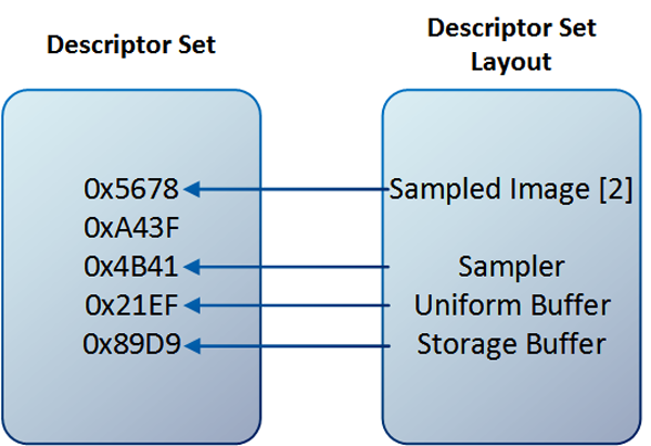
Descriptor set layout creation starts by defining the parameters of all descriptors available in a given set. This is done by filling a structure variable of type VkDescriptorSetLayoutBinding:
VkDescriptorSetLayoutBinding layout_binding = {
  0,                                          // uint32_t             binding
  VK_DESCRIPTOR_TYPE_COMBINED_IMAGE_SAMPLER,  // VkDescriptorType     descriptorType
  1,                                          // uint32_t             descriptorCount
  VK_SHADER_STAGE_FRAGMENT_BIT,               // VkShaderStageFlags   stageFlags
  nullptr                                     // const VkSampler     *pImmutableSamplers
};
13.Tutorial06.cpp, function CreateDescriptorSetLayout()
The above description contains the following members:
- binding – Index of a descriptor within a given set. All descriptors from a single layout (and set) must have a unique binding. This same binding is also used inside shaders to access a descriptor.
- descriptorType – The type of a descriptor (sampler, uniform buffer, and so on.)
- descriptorCount – Number of descriptors of a selected type accessed as an array. For a single descriptor, 1 value should be used.
- stageFlags – Set of flags defining all shader stages that will have access to a given descriptor. For better performance, we should specify only those stages that will access the given resource.
- pImmutableSamplers – Affects only samplers that should be permanently bound into the layout (and cannot be changed later). But we don’t have to worry about this parameter, and we can bind samplers as any other descriptors by setting this parameter to null.
In our example, we want to use only one descriptor of a combined image sampler, which will be accessed only by a fragment shader. It will be the first (binding zero) descriptor in a given layout. To avoid wasting memory, we should keep bindings as compactly as possible (as close to zero as possible), because drivers may allocate memory for descriptor slots even if they are not used.
We can prepare similar parameters for other descriptors accessed from a single set. Then, pointers to such variables are provided to a variable of type VkDescriptorSetLayoutCreateInfo:
VkDescriptorSetLayoutCreateInfo descriptor_set_layout_create_info = {
  VK_STRUCTURE_TYPE_DESCRIPTOR_SET_LAYOUT_CREATE_INFO,  // VkStructureType                      sType
  nullptr,                                              // const void                          *pNext
  0,                                                    // VkDescriptorSetLayoutCreateFlags     flags
  1,                                                    // uint32_t                             bindingCount
  &layout_binding                                       // const VkDescriptorSetLayoutBinding  *pBindings
};

if( vkCreateDescriptorSetLayout( GetDevice(), &descriptor_set_layout_create_info, nullptr, &Vulkan.DescriptorSet.Layout ) != VK_SUCCESS ) {
  std::cout << "Could not create descriptor set layout!" << std::endl;
  return false;
}
14.Tutorial06.cpp, function CreateDescriptorSetLayout()
This structure contains just a few members:
- sType – The type of the structure. It should be equal to VK_STRUCTURE_TYPE_DESCRIPTOR_SET_LAYOUT_CREATE_INFO.
- pNext – Pointer reserved for extensions.
- flags – This parameter allows us to provide additional options for layout creation. But as they are connected with using extensions, we can set this parameter to zero.
- bindingCount – The number of bindings, elements in the pBindings array.
- pBindings – A pointer to an array with descriptions of all resources in a given layout. This array must be no smaller than the value of the bindingCount parameter.
After we have filled in the structure, we can call the vkCreateDescriptorSetLayout() function to create a descriptor set layout. We will need this layout later, multiple times.
Creating a Descriptor Pool
Next step is to prepare a descriptor set. Descriptor sets, similar to command buffers, are not created directly; they are instead allocated from pools. Before we can allocate a descriptor set, we need to create a descriptor pool.
VkDescriptorPoolSize pool_size = {
  VK_DESCRIPTOR_TYPE_COMBINED_IMAGE_SAMPLER,      // VkDescriptorType               type
  1                                               // uint32_t                       descriptorCount
};

VkDescriptorPoolCreateInfo descriptor_pool_create_info = {
  VK_STRUCTURE_TYPE_DESCRIPTOR_POOL_CREATE_INFO,  // VkStructureType                sType
  nullptr,                                        // const void                    *pNext
  0,                                              // VkDescriptorPoolCreateFlags    flags
  1,                                              // uint32_t                       maxSets
  1,                                              // uint32_t                       poolSizeCount
  &pool_size                                      // const VkDescriptorPoolSize    *pPoolSizes
};

if( vkCreateDescriptorPool( GetDevice(), &descriptor_pool_create_info, nullptr, &Vulkan.DescriptorSet.Pool ) != VK_SUCCESS ) {
  std::cout << "Could not create descriptor pool!" << std::endl;
  return false;
}
15.Tutorial06.cpp, function CreateDescriptorPool()
Creating a descriptor pool involves specifying how many descriptor sets can be allocated from it. At the same time, we also need to specify what types of descriptors, and how many of them can be allocated from the pool across all sets. For example, let’s imagine that we want to allocate a single sampled image and a single storage buffer from a given pool, and that we can allocate two descriptor sets from the pool. When doing this, if we allocate one descriptor set with a sampled image, the second descriptor can contain only a storage buffer. If a single descriptor set allocated from that pool contains both resources, we can’t allocate another set because it would have to be empty. During descriptor pool creation we define the total number of descriptors and total number of sets that can be allocated from it. This is done in two steps.
First, we prepare variables of type VkDescriptorPoolSize that specify the type of a descriptor and the total number of descriptors of a selected type that can be allocated from the pool. Next, we provide an array of such variables to a variable of type VkDescriptorPoolCreateInfo. It contains the following members:
- sType – The type of the structure. In this case it should be set to VK_STRUCTURE_TYPE_DESCRIPTOR_POOL_CREATE_INFO.
- pNext – Pointer reserved for extensions.
- flags – This parameter defines (when using a VK_DESCRIPTOR_POOL_CREATE_FREE_DESCRIPTOR_SET_BIT flag) whether individual sets allocated from the pool can be freed or reset separately. If this parameter is set to zero, all descriptor sets allocated from the pool can only be reset at once (in bulk) by resetting the whole pool.
- maxSets – Is the total number of sets that can be allocated from the pool.
- poolSizeCount–Defines the number of elements in the pPoolSizes array.
- pPoolSizes – Is a pointer to an array containing no less than poolSizeCount elements containing descriptor types and a total number of descriptors of that type that can be allocated from the pool.
In our example we want to allocate only a single descriptor set with only one descriptor of a combined image sampler type. We prepare parameters according to our example and create a descriptor pool by calling the vkCreateDescriptorPool() function.
Allocating Descriptor Sets
Now we are ready to allocate the descriptor set itself. Code that does this is quite short:
VkDescriptorSetAllocateInfo descriptor_set_allocate_info = {
  VK_STRUCTURE_TYPE_DESCRIPTOR_SET_ALLOCATE_INFO, // VkStructureType                sType
  nullptr,                                        // const void                    *pNext
  Vulkan.DescriptorSet.Pool,                      // VkDescriptorPool               descriptorPool
  1,                                              // uint32_t                       descriptorSetCount
  &Vulkan.DescriptorSet.Layout                    // const VkDescriptorSetLayout   *pSetLayouts
};

if( vkAllocateDescriptorSets( GetDevice(), &descriptor_set_allocate_info, &Vulkan.DescriptorSet.Handle ) != VK_SUCCESS ) {
  std::cout << "Could not allocate descriptor set!" << std::endl;
  return false;
}
16.Tutorial06.cpp, function AllocateDescriptorSet()
To allocate a descriptor set we need to prepare a variable of VkDescriptorSetAllocateInfo type, which has the following members:
- sType – Standard type of the structure. For the purpose of descriptor set allocation we need to set this member to a value of VK_STRUCTURE_TYPE_DESCRIPTOR_SET_ALLOCATE_INFO.
- pNext – Pointer reserved for extensions.
- descriptorPool – Handle of a descriptor pool from which the command buffer should be allocated.
- descriptorSetCount – Number of descriptor sets we want to allocate (and number of elements in the pSetLayouts member).
- pSetLayouts – Pointer to an array with at least descriptorSetCount elements. Each element of this array must contain a descriptor set layout that defines the inner structure of the allocated descriptor set (elements may repeat; for example, we can allocate five descriptor sets at once, all with the same layout).
As we can see in the above structure, we need to provide descriptor set layouts. That’s why we needed to create them earlier. To allocate a selected number of descriptor sets from a provided pool we need to provide a pointer to the above structure to the vkAllocateDescriptorSets() function.
Updating Descriptor Sets
We prepared a descriptor set, but it is empty; it’s uninitialized. Now we need to fill it or update it. This means that we tell the driver which resources should be used for descriptors inside the set.
We can update a descriptor set in two ways:
- By writing to the descriptor set—this way we provide new resources.
- By copying data from another descriptor set—if we have a previously updated descriptor set and if we also want to use some of its descriptors in another descriptor we can copy them; this approach can be much faster than writing descriptor sets directly from the CPU.
As we don’t have another descriptor set, we need to write to our single descriptor set directly. For each descriptor type we need to prepare two structures. One, common for all descriptor types, is the VkWriteDescriptorSet structure. It contains the following members:
- sType – Type of the structure. We need to use a VK_STRUCTURE_TYPE_WRITE_DESCRIPTOR_SET value.
- pNext – Pointer reserved for extensions.
- dstSet – Handle of a descriptor set that we want to update (fill with specific resources).
- dstBinding – Index within the descriptor set that we want to update. We must provide one of the bindings specified during descriptor set layout creation. What’s more, the selected binding must correspond to a provided type of the descriptor.
- dstArrayElement – Specifies the first array index we want to update. Using a single VkWriteDescriptorSet structure we can update multiple elements of a single array. Let’s say we have a four-element array of samplers and we want to update the last two (with indices 2 and 3); we can provide two samplers and update the array starting from index 2.
- descriptorCount – Number of descriptors we want to update (number of elements in pImageInfo or pBufferInfo, or pTexelBufferView array). For ordinary descriptors we set the value to one. But for arrays we can provide larger values.
- descriptorType – Type of the descriptor we are going to update. It must be the same as the descriptor type provided during descriptor set layout creation with the same binding (index within a descriptor set).
- pImageInfo – Pointer to an array with at least descriptorCount elements of type VkDescriptorImageInfo. Each such element must contain handles of specific resources when we want to update VK_DESCRIPTOR_TYPE_SAMPLER, VK_DESCRIPTOR_TYPE_SAMPLED_IMAGE, VK_DESCRIPTOR_TYPE_COMBINED_IMAGE_SAMPLER, VK_DESCRIPTOR_TYPE_STORAGE_IMAGE, or VK_DESCRIPTOR_TYPE_INPUT_ATTACHMENT descriptors.
- pBufferInfo – Pointer to an array with at least descriptorCount elements of type VkDescriptorBufferInfo. Each such element must contain handles of specific resources when we want to update VK_DESCRIPTOR_TYPE_UNIFORM_BUFFER, VK_DESCRIPTOR_TYPE_STORAGE_BUFFER, VK_DESCRIPTOR_TYPE_UNIFORM_BUFFER_DYNAMIC, or VK_DESCRIPTOR_TYPE_STORAGE_BUFFER_DYNAMIC descriptors.
- pTexelBufferView – Array with at least descriptorCount VkBufferView handles. This array is used when we want to update VK_DESCRIPTOR_TYPE_UNIFORM_BUFFER, VK_DESCRIPTOR_TYPE_STORAGE_BUFFER, VK_DESCRIPTOR_TYPE_UNIFORM_BUFFER_DYNAMIC, or VK_DESCRIPTOR_TYPE_STORAGE_BUFFER_DYNAMIC descriptors.
Depending on the type of descriptor we want to update, we need to prepare a variable (or an array of variables) of type VkDescriptorImageInfo, VkDescriptorBufferInfo, or VkBufferView. Here, we want to update a combined image sampler descriptor, so we need to prepare a variable of type VkDescriptorImageInfo. It contains the following members:
- sampler – Handle of a sampler object.
- imageView – Handle of an image view.
- imageLayout – Here we provide a layout that the image will have when the descriptor is accessed inside shaders.
In this structure we provide parameters of specific resources; we point to created and valid resources that we want to use inside shaders. Members of this structure are initialized based on the descriptor type. For example, if we update a sampler, we need to provide only the handle of a sampler. If we want to update a sampled image, we need to provide an image view’s handle and an image’s layout. But image won’t be transitioned to this layout automatically (as in render passes). We need to perform the transition to this layout ourselves, explicitly through pipeline barriers or, in case of input attachments, through render passes. What’s more, we need to provide a layout that corresponds to a given usage.
In our example we want to use a texture. We can do this either by using separate sampler and sampled image descriptors or by using a combined image sampler descriptor (as in typical OpenGL applications). The latter approach can be more optimal (some hardware platforms may sample data from combined image samplers faster than from separate samplers and sampled images), and we present that approach here. When we want to update a combined image sampler, we need to provide all three members of the VkDescriptorImageInfo structure:
VkDescriptorImageInfo image_info = {
  Vulkan.Image.Sampler,                       // VkSampler                      sampler
  Vulkan.Image.View,                          // VkImageView                    imageView
  VK_IMAGE_LAYOUT_SHADER_READ_ONLY_OPTIMAL    // VkImageLayout                  imageLayout
};

VkWriteDescriptorSet descriptor_writes = {
  VK_STRUCTURE_TYPE_WRITE_DESCRIPTOR_SET,     // VkStructureType                sType
  nullptr,                                    // const void                    *pNext
  Vulkan.DescriptorSet.Handle,                // VkDescriptorSet                dstSet
  0,                                          // uint32_t                       dstBinding
  0,                                          // uint32_t                       dstArrayElement
  1,                                          // uint32_t                       descriptorCount
  VK_DESCRIPTOR_TYPE_COMBINED_IMAGE_SAMPLER,  // VkDescriptorType               descriptorType
  &image_info,                                // const VkDescriptorImageInfo   *pImageInfo
  nullptr,                                    // const VkDescriptorBufferInfo  *pBufferInfo
  nullptr                                     // const VkBufferView            *pTexelBufferView
};

vkUpdateDescriptorSets( GetDevice(), 1, &descriptor_writes, 0, nullptr );
17.Tutorial06.cpp, function UpdateDescriptorSet()
A pointer to a variable of type VkDescriptorImageInfo is then provided in a variable of type VkWriteDescriptorSet. As we update only one descriptor, we need only one instance of both structures. But of course we can update more descriptors at a time, in which case we need to prepare more variables, which are then provided to the vkUpdateDescriptorSets() function.
Creating a Pipeline Layout
We are not yet done. When we want to use descriptors, allocating and updating descriptor sets is not the only job we need to perform. We have prepared specific resources that are almost ready to be used inside shaders, but descriptor sets are used to store handles of specific resources. These handles are provided during command buffer recording. We need to prepare information for the other side of the barricade: the driver also needs to know what types of resources the given pipeline needs access to. This information is crucial when we create a pipeline as it may impact its internal structure or maybe even a shader compilation. And this information is provided in a so-called pipeline layout.
The pipeline layout stores information about resource types that the given pipeline has access to. These resources involve descriptors and push constant ranges. For now we can skip push constants and focus only on descriptors.
To create a pipeline layout and prepare information about the types of resources accessed by the pipeline, we need to provide an array of descriptor set layouts. This is done through the following members of a variable of type VkPipelineLayoutCreateInfo:
- sType – Pointer reserved for extensions.
- flags – This parameter is reserved for future use.
- setLayoutCount – Number of elements in the pSetLayouts member and number of separate descriptor sets that can be used with this pipeline.
- pSetLayouts – Array with descriptor set layouts.
- pushConstantRangeCount – Number of separate push constant ranges.
- pPushConstantRanges – Array with elements describing push constant ranges.
And this is when descriptor set layouts are used again. The single descriptor set layout defines resource types contained within a single descriptor set. And an array of these layouts defines resource types that the given pipeline needs access to.
To create a pipeline layout we just call the vkCreatePipelineLayout() function. We did this in Introduction to Vulkan Part 3: First Triangle. But there we created an empty layout (with no push constants and with no access to descriptor resources). Here, we create a more typical pipeline layout.
VkPipelineLayoutCreateInfo layout_create_info = {
  VK_STRUCTURE_TYPE_PIPELINE_LAYOUT_CREATE_INFO,  // VkStructureType                sType
  nullptr,                                        // const void                    *pNext
  0,                                              // VkPipelineLayoutCreateFlags    flags
  1,                                              // uint32_t                       setLayoutCount
  &Vulkan.DescriptorSet.Layout,                   // const VkDescriptorSetLayout   *pSetLayouts
  0,                                              // uint32_t                       pushConstantRangeCount
  nullptr                                         // const VkPushConstantRange     *pPushConstantRanges
};

if( vkCreatePipelineLayout( GetDevice(), &layout_create_info, nullptr, &Vulkan.PipelineLayout ) != VK_SUCCESS ) {
  std::cout << "Could not create pipeline layout!" << std::endl;
  return false;
}
return true;
18.Tutorial06.cpp, function CreatePipelineLayout()
Such layout is then provided during pipeline creation. We also need to use this layout when we bind descriptor sets during command buffer recording. So we need to store the pipeline layout handle.
Binding Descriptor Sets
One last thing is to bind descriptor sets to the command buffer during recording. We can have multiple different descriptor sets or multiple, similar descriptor sets (with the same layouts), but they may contain different resource handles. Which of these descriptors are used during rendering is defined during command buffer recording. Before we can draw anything, we need to set up a valid state (according to the drawing parameters). For each command buffer we record we need to do it from scratch.
Drawing operations requires us to use render passes and pipelines. If a pipeline uses descriptor resources (when shaders access images or buffers), we need to bind descriptor sets by calling the vkCmdBindDescriptorSets() function. For this function we must provide a handle of the pipeline layout and an array of descriptor set handles. We bind descriptor sets to specific indices. The given index we bind a descriptor set to must correspond to its layout provided at the same index during pipeline creation.
vkCmdBeginRenderPass( command_buffer, &render_pass_begin_info, VK_SUBPASS_CONTENTS_INLINE );

vkCmdBindPipeline( command_buffer, VK_PIPELINE_BIND_POINT_GRAPHICS, Vulkan.GraphicsPipeline );

// ...

vkCmdBindDescriptorSets( command_buffer, VK_PIPELINE_BIND_POINT_GRAPHICS, Vulkan.PipelineLayout, 0, 1, &Vulkan.DescriptorSet.Handle, 0, nullptr );

vkCmdDraw( command_buffer, 4, 1, 0, 0 );

vkCmdEndRenderPass( command_buffer );
19.Tutorial06.cpp, function PrepareFrame()
Accessing Descriptors in Shaders
One more thing. We need to write proper shaders. In this example, we access a texture inside a fragment shader only, so only the fragment shader will be presented.
From the beginning of this tutorial we have been referring to descriptor sets, bindings within descriptor sets, and about binding descriptor sets themselves. At the same time, we may have multiple descriptor sets bound to a command buffer. Each descriptor set may contain multiple resources. This data conforms to a specific address that we use inside shaders. This address is defined through a layout() specifier like this:
layout(set=S, binding=B) uniform <variable type> <variable name>
Set defines an index that the given descriptor set was bound to through the vkCmdBindDescriptorSets() function. Binding specifies the index of a resource within the provided set and corresponds to the binding defined during descriptor set layout creation. In our case, we have only one descriptor set provided at index zero, with only one combined image sampler at binding zero. Combined image samplers are accessed inside shaders through sampler1D, sampler2D, or sampler 3D variables. So our fragment shader’s source code looks like this:
#version 450

layout(set=0, binding=0) uniform sampler2D u_Texture;

layout(location = 0) in vec2 v_Texcoord;

layout(location = 0) out vec4 o_Color;

void main() {
  o_Color = texture( u_Texture, v_Texcoord );
}
20.shader.frag, -
Tutorial06 Execution
We can see below how the final image generated by the sample program should look:

We render a quad that has a texture applied to its surface. The quad should adjust its size (and aspect) to match the window’s size and shape (if we stretch the window, the quad and the image will be stretched too).
Cleaning Up
Before we can end our application, we should perform a cleanup.
// ...

if( Vulkan.GraphicsPipeline != VK_NULL_HANDLE ) {
  vkDestroyPipeline( GetDevice(), Vulkan.GraphicsPipeline, nullptr );
  Vulkan.GraphicsPipeline = VK_NULL_HANDLE;
}

if( Vulkan.PipelineLayout != VK_NULL_HANDLE ) {
  vkDestroyPipelineLayout( GetDevice(), Vulkan.PipelineLayout, nullptr );
  Vulkan.PipelineLayout = VK_NULL_HANDLE;
}

// ...

if( Vulkan.DescriptorSet.Pool != VK_NULL_HANDLE ) {
  vkDestroyDescriptorPool( GetDevice(), Vulkan.DescriptorSet.Pool, nullptr );
  Vulkan.DescriptorSet.Pool = VK_NULL_HANDLE;
}

if( Vulkan.DescriptorSet.Layout != VK_NULL_HANDLE ) {
  vkDestroyDescriptorSetLayout( GetDevice(), Vulkan.DescriptorSet.Layout, nullptr );
  Vulkan.DescriptorSet.Layout = VK_NULL_HANDLE;
}

if( Vulkan.Image.Sampler != VK_NULL_HANDLE ) {
  vkDestroySampler( GetDevice(), Vulkan.Image.Sampler, nullptr );
  Vulkan.Image.Sampler = VK_NULL_HANDLE;
}

if( Vulkan.Image.View != VK_NULL_HANDLE ) {
  vkDestroyImageView( GetDevice(), Vulkan.Image.View, nullptr );
  Vulkan.Image.View = VK_NULL_HANDLE;
}

if( Vulkan.Image.Handle != VK_NULL_HANDLE ) {
  vkDestroyImage( GetDevice(), Vulkan.Image.Handle, nullptr );
  Vulkan.Image.Handle = VK_NULL_HANDLE;
}

if( Vulkan.Image.Memory != VK_NULL_HANDLE ) {
  vkFreeMemory( GetDevice(), Vulkan.Image.Memory, nullptr );
  Vulkan.Image.Memory = VK_NULL_HANDLE;
}
21.Tutorial06.cpp, function destructor
We destroy both pipeline and its layout by calling the vkDestroyPipeline() and vkDestroyPipelineLayout() functions. Next, we destroy the descriptor pool with the vkDestroyDescriptorPool() function and the descriptor set layout with the vkDestroyDescriptorSetLayout() function. We of course destroy other resources, but we already know how to do this. You may notice that we don’t free a descriptor set. We can free each descriptor set separately if a proper flag was provided during descriptor pool creation. But we don’t have to—when we destroy a descriptor pool all sets allocated from this pool are also freed.
Conclusion
This part of the tutorial presented a way to use textures (combined image samplers, in fact) inside shaders. To do this we created an image and allocated and bound a memory to it. We also created an image view. Next, we copied data from a staging buffer to the image to initialize its contents. We also created a sampler object that defined a way in which image data was read inside shaders.
Next, we prepared a descriptor set. First, we created a descriptor set layout. After that, a descriptor pool was created from which a single descriptor set was allocated. We updated this set with the sampler and the image view handles.
The descriptor set layout was also used to define resources to which our graphics pipeline had access. This was done during pipeline layout creation. This layout was then used when we bound the descriptor sets to a command buffer.
We also learned how to prepare a shader code that accessed the combined image sampler to read its data (to sample it as a texture). It was done inside a fragment shader that was used during rendering of our simple geometry. This way we applied a texture to the surface of this geometry.
Next Up: Uniform Buffers- Using Buffers in Shaders
This sample source code is released under the Intel Sample Source Code License Agreement.