View PDF [723KB]
Back to: Part 4 Vertex Attributes
Next up: Part 6 Descriptor Sets
Tutorial 5: Staging Resources – Copying Data between Buffers
In this part of the tutorial we will focus on improving performance. At the same time, we will prepare for the next tutorial, in which we introduce images and descriptors (shader resources). Using the knowledge we gather here, it will be easier for us to follow the next part and squeeze as much performance as possible from our graphics hardware.
What are “staging resources” or “staging buffers”? They are intermediate or temporary resources used to transfer data from an application (CPU) to a graphics card’s memory (GPU). We need them to increase our application’s performance.
In Part 4 of the tutorial we learned how to use buffers, bind them to a host‑visible memory, map this memory, and transfer data from the CPU to the GPU. This approach is easy and convenient for us, but we need to know that host‑visible parts of a graphics card’s memory aren’t the most efficient. Typically, they are much slower than the parts of the memory that are not directly accessible to the application (cannot be mapped by an application). This causes our application to execute in a sub-optimal way.
One solution to this problem is to always use device-local memory for all resources involved in a rendering process. But as device-local memory isn’t accessible for an application, we cannot directly transfer any data from the CPU to such memory. That’s why we need intermediate, or staging, resources.
In this part of the tutorial we will bind the buffer with vertex attribute data to the device-local memory. And we will use the staging buffer to mediate the transfer of data from the CPU to the vertex buffer.
Again, only the differences between this tutorial and the previous tutorial (Part 4) are described.
Creating Rendering Resources
This time I have moved rendering resources creation to the beginning of our code. Later we will need to record and submit a command buffer to transfer data from the staging resource to the vertex buffer. I have also refactored rendering resource creation code to eliminate multiple loops and replace them with only one loop. In this loop we can create all resources that compose our virtual frame.
bool Tutorial05::CreateRenderingResources() {
  if( !CreateCommandPool( GetGraphicsQueue().FamilyIndex, &Vulkan.CommandPool ) ) {
    return false;
  }

  for( size_t i = 0; i < Vulkan.RenderingResources.size(); ++i ) {
    if( !AllocateCommandBuffers( Vulkan.CommandPool, 1, &Vulkan.RenderingResources[i].CommandBuffer ) ) {
      return false;
    }

    if( !CreateSemaphore( &Vulkan.RenderingResources[i].ImageAvailableSemaphore ) ) {
      return false;
    }

    if( !CreateSemaphore( &Vulkan.RenderingResources[i].FinishedRenderingSemaphore ) ) {
      return false;
    }

    if( !CreateFence( VK_FENCE_CREATE_SIGNALED_BIT, &Vulkan.RenderingResources[i].Fence ) ) {
      return false;
    }
  }
  return true;
}

bool Tutorial05::CreateCommandPool( uint32_t queue_family_index, VkCommandPool *pool ) {
  VkCommandPoolCreateInfo cmd_pool_create_info = {
    VK_STRUCTURE_TYPE_COMMAND_POOL_CREATE_INFO,       // VkStructureType                sType
    nullptr,                                          // const void                    *pNext
    VK_COMMAND_POOL_CREATE_RESET_COMMAND_BUFFER_BIT | // VkCommandPoolCreateFlags       flags
    VK_COMMAND_POOL_CREATE_TRANSIENT_BIT,
    queue_family_index                                // uint32_t                       queueFamilyIndex
  };

  if( vkCreateCommandPool( GetDevice(), &cmd_pool_create_info, nullptr, pool ) != VK_SUCCESS ) {
    std::cout << "Could not create command pool!" << std::endl;
    return false;
  }
  return true;
}

bool Tutorial05::AllocateCommandBuffers( VkCommandPool pool, uint32_t count, VkCommandBuffer *command_buffers ) {
  VkCommandBufferAllocateInfo command_buffer_allocate_info = {
    VK_STRUCTURE_TYPE_COMMAND_BUFFER_ALLOCATE_INFO,   // VkStructureType                sType
    nullptr,                                          // const void                    *pNext
    pool,                                             // VkCommandPool                  commandPool
    VK_COMMAND_BUFFER_LEVEL_PRIMARY,                  // VkCommandBufferLevel           level
    count                                             // uint32_t                       bufferCount
  };

  if( vkAllocateCommandBuffers( GetDevice(), &command_buffer_allocate_info, command_buffers ) != VK_SUCCESS ) {
    std::cout << "Could not allocate command buffer!" << std::endl;
    return false;
  }
  return true;
}

bool Tutorial05::CreateSemaphore( VkSemaphore *semaphore ) {
  VkSemaphoreCreateInfo semaphore_create_info = {
    VK_STRUCTURE_TYPE_SEMAPHORE_CREATE_INFO,          // VkStructureType                sType
    nullptr,                                          // const void*                    pNext
    0                                                 // VkSemaphoreCreateFlags         flags
  };

  if( vkCreateSemaphore( GetDevice(), &semaphore_create_info, nullptr, semaphore ) != VK_SUCCESS ) {
    std::cout << "Could not create semaphore!" << std::endl;
    return false;
  }
  return true;
}

bool Tutorial05::CreateFence( VkFenceCreateFlags flags, VkFence *fence ) {
  VkFenceCreateInfo fence_create_info = {
    VK_STRUCTURE_TYPE_FENCE_CREATE_INFO,              // VkStructureType                sType
    nullptr,                                          // const void                    *pNext
    flags                                             // VkFenceCreateFlags             flags
  };

  if( vkCreateFence( GetDevice(), &fence_create_info, nullptr, fence ) != VK_SUCCESS ) {
    std::cout << "Could not create a fence!" << std::endl;
    return false;
  }
  return true;
}
1.	Tutorial05.cpp
1. Tutorial05.cpp
First we create a command pool for which we indicate that command buffers allocated from this pool will be short lived. In our case, all command buffers will be submitted only once before rerecording.
Next we iterate over the arbitrary chosen number of virtual frames. In this code example, the number of virtual frames is three. Inside the loop, for each virtual frame, we allocate one command buffer, create two semaphores (one for image acquisition and a second to indicate that frame rendering is done) and a fence. Framebuffer creation is done inside a drawing function, just before command buffer recording.
This is the same set of rendering resources used in Part 4, where you can find a more thorough explanation of what is going on in the code. I will also skip render pass and graphics pipeline creation. They are created in exactly the same way they were created previously. Since nothing has changed here, we will jump directly to buffer creation.
Buffer creation
Here is our general code used for buffer creation:
VkBufferCreateInfo buffer_create_info = {
  VK_STRUCTURE_TYPE_BUFFER_CREATE_INFO,             // VkStructureType                sType
  nullptr,                                          // const void                    *pNext
  0,                                                // VkBufferCreateFlags            flags
  buffer.Size,                                      // VkDeviceSize                   size
  usage,                                            // VkBufferUsageFlags             usage
  VK_SHARING_MODE_EXCLUSIVE,                        // VkSharingMode                  sharingMode
  0,                                                // uint32_t                       queueFamilyIndexCount
  nullptr                                           // const uint32_t                *pQueueFamilyIndices
};

if( vkCreateBuffer( GetDevice(), &buffer_create_info, nullptr, &buffer.Handle ) != VK_SUCCESS ) {
  std::cout << "Could not create buffer!" << std::endl;
  return false;
}

if( !AllocateBufferMemory( buffer.Handle, memoryProperty, &buffer.Memory ) ) {
  std::cout << "Could not allocate memory for a buffer!" << std::endl;
  return false;
}

if( vkBindBufferMemory( GetDevice(), buffer.Handle, buffer.Memory, 0 ) != VK_SUCCESS ) {
  std::cout << "Could not bind memory to a buffer!" << std::endl;
  return false;
}

return true;
2. Tutorial05.cpp, function CreateBuffer()
The code is wrapped into a CreateBuffer() function, which accepts the buffer’s usage, size, and requested memory properties. To create a buffer we need to prepare a variable of type VkBufferCreateInfo. It is a structure that contains the following members:
- sType – Standard type of the structure. Here it should be equal to VK_STRUCTURE_TYPE_BUFFER_CREATE_INFO.
- pNext – Pointer reserved for extensions.
- flags – Parameter describing additional properties of the buffer. Right now we can only specify that the buffer can be backed by a sparse memory.
- size – Size of the buffer (in bytes).
- usage – Bitfield indicating intended usages of the buffer.
- sharingMode – Queue sharing mode.
- queueFamilyIndexCount – Number of different queue families that will access the buffer in case of a concurrent sharing mode.
- pQueueFamilyIndices – Array with indices of all queue families that will access the buffer when concurrent sharing mode is used.
Right now we are not interested in binding a sparse memory. We do not want to share the buffer between different device queues, so sharingMode, queueFamilyIndexCount, and pQueueFamilyIndices parameters are irrelevant. The most important parameters are size and usage. We are not allowed to use a buffer in a way that is not specified during buffer creation. Finally, we need to create a buffer that is large enough to contain our data.
To create a buffer we call the vkCreateBuffer() function, which when successful stores the buffer handle in a variable we provided the address of. But creating a buffer is not enough. A buffer, after creation, doesn’t have any storage. We need to bind a memory object (or part of it) to the buffer to back its storage. Or, if we don’t have any memory objects, we need to allocate one.
Each buffer’s usage may have a different memory requirement, which is relevant when we want to allocate a memory object and bind it to the buffer. Here is a code sample that allocates a memory object for a given buffer:
VkMemoryRequirements buffer_memory_requirements;
vkGetBufferMemoryRequirements( GetDevice(), buffer, &buffer_memory_requirements );

VkPhysicalDeviceMemoryProperties memory_properties;
vkGetPhysicalDeviceMemoryProperties( GetPhysicalDevice(), &memory_properties );

for( uint32_t i = 0; i < memory_properties.memoryTypeCount; ++i ) {
  if( (buffer_memory_requirements.memoryTypeBits & (1 << i)) &&
      ((memory_properties.memoryTypes[i].propertyFlags & property) == property) ) {

    VkMemoryAllocateInfo memory_allocate_info = {
      VK_STRUCTURE_TYPE_MEMORY_ALLOCATE_INFO,       // VkStructureType                sType
      nullptr,                                      // const void                    *pNext
      buffer_memory_requirements.size,              // VkDeviceSize                   allocationSize
      i                                             // uint32_t                       memoryTypeIndex
    };

    if( vkAllocateMemory( GetDevice(), &memory_allocate_info, nullptr, memory ) == VK_SUCCESS ) {
      return true;
    }
  }
}
return false;
3. Tutorial05.cpp, function AllocateBufferMemory()
Similarly to the code in Part 4, we first check what the memory requirements for a given buffer are. After that we check the properties of a memory available in a given physical device. It contains information about the number of memory heaps and their capabilities.
Next we iterate over each available memory type and check if it is compatible with the requirement queried for a given buffer. We also check if a given memory type supports our additional, requested properties, for example, whether a given memory type is host-visible. When we find a match, we fill in a VkMemoryAllocateInfo structure and call a vkAllocateMemory() function.
The allocated memory object is then bound to our buffer, and from now on we can safely use this buffer in our application.
Vertex Buffer Creation
The first buffer we want to create is a vertex buffer. It stores data for vertex attributes that are used during rendering. In this example we store position and color for four vertices of a quad. The most important change from the previous tutorial is the use of a device-local memory instead of a host-visible memory. Device-local memory is much faster, but we can’t copy any data directly from the application to device-local memory. We need to use a staging buffer, from which we copy data to the vertex buffer.
We also need to specify two different usages for this buffer. The first is a vertex buffer usage, which means that we want to use the given buffer as a vertex buffer from which data for the vertex attributes will be fetched. The second is transfer dst usage, which means that we will copy data to this buffer. It will be used as a destination of any transfer (copy) operation.
The code that creates a buffer with all these requirements looks like this:
const std::vector<float>& vertex_data = GetVertexData();

Vulkan.VertexBuffer.Size = static_cast<uint32_t>(vertex_data.size() * sizeof(vertex_data[0]));
if( !CreateBuffer( VK_BUFFER_USAGE_VERTEX_BUFFER_BIT | VK_BUFFER_USAGE_TRANSFER_DST_BIT, VK_MEMORY_PROPERTY_DEVICE_LOCAL_BIT, Vulkan.VertexBuffer ) ) {
  std::cout << "Could not create vertex buffer!" << std::endl;
  return false;
}

return true;
4. Tutorial05.cpp, function CreateVertexBuffer()
At the beginning we get the vertex data (hard-coded in a GetVertexData() function) to check how much space we need to hold values for all our vertices. After that we call a CreateBuffer() function presented earlier to create a vertex buffer and bind a device-local memory to it.
Staging Buffer Creation
Next we can create an intermediate staging buffer. This buffer is not used during the rendering process so it can be bound to a slower, host-visible memory. This way we can map it and copy data directly from the application. After that we can copy data from the staging buffer to any other buffer (or even image) that is bound to device-local memory. This way all resources that are used for rendering purposes are bound to the fastest available memory. We just need additional operations for the data transfer.
Here is a code that creates a staging buffer:
Vulkan.StagingBuffer.Size = 4000;
if( !CreateBuffer( VK_BUFFER_USAGE_TRANSFER_SRC_BIT, VK_MEMORY_PROPERTY_HOST_VISIBLE_BIT, Vulkan.StagingBuffer ) ) {
  std::cout << "Could not staging buffer!" << std::endl;
  return false;
}

return true;
5. Tutorial04.cpp, function CreateStagingBuffer()
We will copy data from this buffer to other resources, so we must specify a transfer src usage for it (it will be used as a source for transfer operations). We would also like to map it to be able to directly copy any data from the application. For this we need to use a host-visible memory and that’s why we specify this memory property. The buffer’s size is chosen arbitrarily, but should be large enough to be able to hold vertex data. In real-life scenarios we should try to reuse the staging buffer as many times as possible, in many cases, so its size should be big enough to cover most of data transfer operations in our application. Of course, if we want to do many transfer operations at the same time, we have to create multiple staging buffers.
Copying Data between Buffers
We have created two buffers: one for the vertex attributes data and the other to act as an intermediate buffer. Now we need to copy data from the CPU to the GPU. To do this we need to map the staging buffer and acquire a pointer that we can use to upload data to the graphics hardware’s memory. After that we need to record and submit a command buffer that will copy the vertex data from the staging buffer to the vertex buffer. And as all of our command buffers used for virtual frames and rendering are marked as short lived, we can safely use one of them for this operation.
First let’s see what our data for vertex attributes looks like:
static const std::vector<float> vertex_data = {
  -0.7f, -0.7f, 0.0f, 1.0f,
  1.0f, 0.0f, 0.0f, 0.0f,
  //
  -0.7f, 0.7f, 0.0f, 1.0f,
  0.0f, 1.0f, 0.0f, 0.0f,
  //
  0.7f, -0.7f, 0.0f, 1.0f,
  0.0f, 0.0f, 1.0f, 0.0f,
  //
  0.7f, 0.7f, 0.0f, 1.0f,
  0.3f, 0.3f, 0.3f, 0.0f
};

return vertex_data;
6. Tutorial05.cpp, function GetVertexData()
It is a simple, hard-coded array of floating point values. Data for each vertex contains four components for position attribute and four components for color attribute. As we render a quad, we have four pairs of such attributes.
Here is the code that copies data from the application to the staging buffer and after that from the staging buffer to the vertex buffer:
// Prepare data in a staging buffer
const std::vector<float>& vertex_data = GetVertexData();

void *staging_buffer_memory_pointer;
if( vkMapMemory( GetDevice(), Vulkan.StagingBuffer.Memory, 0, Vulkan.VertexBuffer.Size, 0, &staging_buffer_memory_pointer) != VK_SUCCESS ) {
  std::cout << "Could not map memory and upload data to a staging buffer!" << std::endl;
  return false;
}

memcpy( staging_buffer_memory_pointer, &vertex_data[0], Vulkan.VertexBuffer.Size );

VkMappedMemoryRange flush_range = {
  VK_STRUCTURE_TYPE_MAPPED_MEMORY_RANGE,            // VkStructureType                        sType
  nullptr,                                          // const void                            *pNext
  Vulkan.StagingBuffer.Memory,                      // VkDeviceMemory                         memory
  0,                                                // VkDeviceSize                           offset
  Vulkan.VertexBuffer.Size                          // VkDeviceSize                           size
};
vkFlushMappedMemoryRanges( GetDevice(), 1, &flush_range );

vkUnmapMemory( GetDevice(), Vulkan.StagingBuffer.Memory );

// Prepare command buffer to copy data from staging buffer to a vertex buffer
VkCommandBufferBeginInfo command_buffer_begin_info = {
  VK_STRUCTURE_TYPE_COMMAND_BUFFER_BEGIN_INFO,      // VkStructureType                        sType
  nullptr,                                          // const void                            *pNext
  VK_COMMAND_BUFFER_USAGE_ONE_TIME_SUBMIT_BIT,      // VkCommandBufferUsageFlags              flags
  nullptr                                           // const VkCommandBufferInheritanceInfo  *pInheritanceInfo
};

VkCommandBuffer command_buffer = Vulkan.RenderingResources[0].CommandBuffer;

vkBeginCommandBuffer( command_buffer, &command_buffer_begin_info);

VkBufferCopy buffer_copy_info = {
  0,                                                // VkDeviceSize                           srcOffset
  0,                                                // VkDeviceSize                           dstOffset
  Vulkan.VertexBuffer.Size                          // VkDeviceSize                           size
};
vkCmdCopyBuffer( command_buffer, Vulkan.StagingBuffer.Handle, Vulkan.VertexBuffer.Handle, 1, &buffer_copy_info );

VkBufferMemoryBarrier buffer_memory_barrier = {
  VK_STRUCTURE_TYPE_BUFFER_MEMORY_BARRIER,          // VkStructureType                        sType;
  nullptr,                                          // const void                            *pNext
  VK_ACCESS_MEMORY_WRITE_BIT,                       // VkAccessFlags                          srcAccessMask
  VK_ACCESS_VERTEX_ATTRIBUTE_READ_BIT,              // VkAccessFlags                          dstAccessMask
  VK_QUEUE_FAMILY_IGNORED,                          // uint32_t                               srcQueueFamilyIndex
  VK_QUEUE_FAMILY_IGNORED,                          // uint32_t                               dstQueueFamilyIndex
  Vulkan.VertexBuffer.Handle,                       // VkBuffer                               buffer
  0,                                                // VkDeviceSize                           offset
  VK_WHOLE_SIZE                                     // VkDeviceSize                           size
};
vkCmdPipelineBarrier( command_buffer, VK_PIPELINE_STAGE_TRANSFER_BIT, VK_PIPELINE_STAGE_VERTEX_INPUT_BIT, 0, 0, nullptr, 1, &buffer_memory_barrier, 0, nullptr );

vkEndCommandBuffer( command_buffer );

// Submit command buffer and copy data from staging buffer to a vertex buffer
VkSubmitInfo submit_info = {
  VK_STRUCTURE_TYPE_SUBMIT_INFO,                    // VkStructureType                        sType
  nullptr,                                          // const void                            *pNext
  0,                                                // uint32_t                               waitSemaphoreCount
  nullptr,                                          // const VkSemaphore                     *pWaitSemaphores
  nullptr,                                          // const VkPipelineStageFlags            *pWaitDstStageMask;
  1,                                                // uint32_t                               commandBufferCount
  &command_buffer,                                  // const VkCommandBuffer                 *pCommandBuffers
  0,                                                // uint32_t                               signalSemaphoreCount
  nullptr                                           // const VkSemaphore                     *pSignalSemaphores
};

if( vkQueueSubmit( GetGraphicsQueue().Handle, 1, &submit_info, VK_NULL_HANDLE ) != VK_SUCCESS ) {
  return false;
}

vkDeviceWaitIdle( GetDevice() );

return true;
7. Tutorial05.cpp, function CopyVertexData()
At the beginning, we get vertex data and map the staging buffer’s memory by calling the vkMapMemory() function. During the call, we specify a handle of a memory that is bound to a staging buffer, and buffer’s size. This gives us a pointer that we can use in an ordinary memcpy() function to copy data from our application to graphics hardware.
Next we flush the mapped memory to tell the driver which parts of a memory object were modified. We can specify multiple ranges of memory if needed. We have one memory area that should be flushed and we specify it by creating a variable of type VkMappedMemoryRange and by calling a vkFlushMappedMemoryRanges() function. After that we unmap the memory, but we don’t have to do this. We can keep a pointer for later use and this should not affect the performance of our application.
Next we start preparing a command buffer. We specify that it will be submitted only once before it will be reset. We fill a VkCommandBufferBeginInfo structure and provide it to a vkBeginCommandBuffer() function.
Now we perform the copy operation. First a variable of type VkBufferCopy is created. It contains the following fields:
- srcOffset – Offset in bytes in a source buffer from which we want to copy data.
- dstOffset – Offset in bytes in a destination buffer into which we want to copy data.
- size – Size of the data (in bytes) we want to copy.
We copy data from the beginning of a staging buffer and to the beginning of a vertex buffer, so we specify zero for both offsets. The size of the vertex buffer was calculated based on the hard-coded vertex data, so we copy the same number of bytes. To copy data from one buffer to another, we call a vkCmdCopyBuffer() function.
Setting a Buffer Memory Barrier
We have recorded a copy operation but that’s not all. From now on we will not use the buffer as a target for transfer operations but as a vertex buffer. We need to tell the driver that the type of buffer’s memory access will change and from now on it will serve as a source of data for vertex attributes. To do this we set a memory barrier similarly to what we have done earlier in case of swapchain images.
First we prepare a variable of type VkBufferMemoryBarrier, which contains the following members:
- sType – Standard structure type, here set to VK_STRUCTURE_TYPE_BUFFER_MEMORY_BARRIER.
- pNext – Parameter reserved for extensions.
- srcAccessMask – Types of memory operations that were performed on this buffer before the barrier.
- dstAccessMask – Memory operations that will be performed on a given buffer after the barrier.
- srcQueueFamilyIndex – Index of a queue family that accessed the buffer before.
- dstQueueFamilyIndex – Queue family that will access the buffer from now on.
- buffer – Handle to the buffer for which we set up a barrier.
- offset – Memory offset from the start of the buffer (from the memory’s base offset bound to the buffer).
- size – Size of the buffer’s memory area for which we want to setup a barrier.
As you can see, we can set up a barrier for a specific range of buffer’s memory. But here we do it for the whole buffer, so we specify an offset of 0 and the VK_WHOLE_SIZE enum for the size. We don’t want to transfer ownership between different queue families, so we use VK_QUEUE_FAMILY_IGNORED enum both for srcQueueFamilyIndex and dstQueueFamilyIndex.
The most important parameters are srcAccessMask and dstAccessMask. We have copied data from the staging buffer to a vertex buffer. So before the barrier, the vertex buffer was used as a destination for transfer operations and its memory was written to. That’s why we have specified VK_ACCESS_MEMORY_WRITE_BIT for a srcAccessMask field. But after that the barrier buffer will be used only as a source of data for vertex attributes. So for dstAccessMask field we specify VK_ACCESS_VERTEX_ATTRIBUTE_READ_BIT.
To set up a barrier we call a vkCmdPipelineBarrier() function. And to finish command buffer recording, we call vkEndCommandBuffer(). Next, for all of the above operations to execute, we submit a command buffer by calling vkQueueSubmit() function.
Normally during the command buffer submission, we should provide a fence. It is signaled once all transfer operations (and whole command buffer) are finished. But here, for the sake of simplicity, we call vkDeviceWaitIdle() and wait for all operations executed on a given device to finish. Once all operations complete, we have successfully transferred data to the device-local memory and we can use the vertex buffer without worrying about performance loss.
Tutorial05 Execution
The results of the rendering operations are exactly the same as in Part 4:
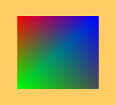
We render a quad that has different colors in each corner: red, green, dark gray, and blue. The quad should adjust its size (and aspect) to match window’s size and shape.
Cleaning Up
In this part of the tutorial, I have also refactored the cleaning code. We have created two buffers, each with a separate memory object. To avoid code redundancy, I prepared a buffer cleaning function:
if( buffer.Handle != VK_NULL_HANDLE ) {
  vkDestroyBuffer( GetDevice(), buffer.Handle, nullptr );
  buffer.Handle = VK_NULL_HANDLE;
}

if( buffer.Memory != VK_NULL_HANDLE ) {
  vkFreeMemory( GetDevice(), buffer.Memory, nullptr );
  buffer.Memory = VK_NULL_HANDLE;
}
8. Tutorial05.cpp, function DestroyBuffer()
This function checks whether a given buffer was successfully created, and if so it calls a vkDestroyBuffer() function. It also frees memory associated with a given buffer through a vkFreeMemory() function call. The DestroyBuffer() function is called in a destructor that also releases all other resources relevant to this part of the tutorial:
if( GetDevice() != VK_NULL_HANDLE ) {
  vkDeviceWaitIdle( GetDevice() );

  DestroyBuffer( Vulkan.VertexBuffer );

  DestroyBuffer( Vulkan.StagingBuffer );

  if( Vulkan.GraphicsPipeline != VK_NULL_HANDLE ) {
    vkDestroyPipeline( GetDevice(), Vulkan.GraphicsPipeline, nullptr );
    Vulkan.GraphicsPipeline = VK_NULL_HANDLE;
  }

  if( Vulkan.RenderPass != VK_NULL_HANDLE ) {
    vkDestroyRenderPass( GetDevice(), Vulkan.RenderPass, nullptr );
    Vulkan.RenderPass = VK_NULL_HANDLE;
  }

  for( size_t i = 0; i < Vulkan.RenderingResources.size(); ++i ) {
    if( Vulkan.RenderingResources[i].Framebuffer != VK_NULL_HANDLE ) {
      vkDestroyFramebuffer( GetDevice(), Vulkan.RenderingResources[i].Framebuffer, nullptr );
    }
    if( Vulkan.RenderingResources[i].CommandBuffer != VK_NULL_HANDLE ) {
      vkFreeCommandBuffers( GetDevice(), Vulkan.CommandPool, 1, &Vulkan.RenderingResources[i].CommandBuffer );
    }
    if( Vulkan.RenderingResources[i].ImageAvailableSemaphore != VK_NULL_HANDLE ) {
      vkDestroySemaphore( GetDevice(), Vulkan.RenderingResources[i].ImageAvailableSemaphore, nullptr );
    }
    if( Vulkan.RenderingResources[i].FinishedRenderingSemaphore != VK_NULL_HANDLE ) {
      vkDestroySemaphore( GetDevice(), Vulkan.RenderingResources[i].FinishedRenderingSemaphore, nullptr );
    }
    if( Vulkan.RenderingResources[i].Fence != VK_NULL_HANDLE ) {
      vkDestroyFence( GetDevice(), Vulkan.RenderingResources[i].Fence, nullptr );
    }
  }

  if( Vulkan.CommandPool != VK_NULL_HANDLE ) {
    vkDestroyCommandPool( GetDevice(), Vulkan.CommandPool, nullptr );
    Vulkan.CommandPool = VK_NULL_HANDLE;
  }
}
9. Tutorial05.cpp, destructor
First we wait for all the operations performed by the device to finish. Next we destroy the vertex and staging buffers. After that we destroy all other resources in the order opposite to their creation: graphics pipeline, render pass, and resources for each virtual frame, which consists of a framebuffer, command buffer, two semaphores, a fence, and a framebuffer. Finally we destroy a command pool from which command buffers were allocated.
Conclusion
In this tutorial we used the recommended technique for transferring data from the application to the graphics hardware. It gives the best performance for the resources involved in the rendering process and the ability to map and copy data from the application to the staging buffer. We only need to prepare an additional command buffer recording and submission to transfer data from one buffer to another.
Using staging buffers is recommended for more than just copying data between buffers. We can use the same approach to copy data from a buffer to images. And the next part of the tutorial will show how to do this by presenting the descriptors, descriptor sets, and descriptor layouts, which are another big part of the Vulkan API.
Next up: API without Secrets: Introduction to Vulkan* Part 6
This sample source code is released under the Intel Sample Source Code License Agreement.