About this Tutorial
This is part 4 of a 4-part tutorial series that shows you how to manage the DE10-Nano with Azure IoT Edge and use container-based virtualization to reprogram the onboard FPGA from the Azure Cloud.
Objectives
In this tutorial, you learn how to:
- Re-configure the FPGA using Device Tree Overlay
- Create a Device Tree Overlay file
- Create a Device Tree Overlay to re-configure the FPGA from Container
Prerequisites
- Complete the previous tutorial: Build an IoT Edge Module that Gathers Sensor Data and Store it in the Azure* Container Registry (ACR)
- An Azure IoT Hub
- An IoT Edge device (DE10-Nano) with IoT Edge runtime installed
- An Azure Container Registry (ACR)
- Display Monitor with HDMI port (and HDMI cord)
Software to install later in this tutorial
Intel® SoC FPGA Embedded Development Suite (SoC EDS) Standard Edition version 20.1: Contains the Device Tree Compiler, which compiles Device Tree Source files, and we use it to create a Device Tree Blob file.
Files Required in this Tutorial
If you have not done so already, please get the files from the GitHub repository.
Open a terminal to get the source code.
sudo apt install git
cd ~/Download
git clone https://github.com/intel-iot-devkit/terasic-de10-nano-kit
This repository does not only contain the files for these tutorials (Module 3 and Module 4) but other tutorial files.
In this tutorial, we will be using files located in: ~/Downloads/terasic-de10-nano/azure-de10nano-document/module04-device-tree-overlay-guide
Section A: Re-configure FPGA via Device Tree Overlay (DTO) and FPGA Region
Utilize the Device Tree and Device Tree Overlay functions to access the FPGA Region driver and re-configure the FPGA. The Appendix of this tutorial describes the Device Tree, Device Tree Overlay, and FPGA Region driver.
Step 1: Create a Device Tree Overlay file
Let's create a device tree overlay file for FPGA configuration. Create a file with the following content using your favorite text editor such as vim, and save it as config_only.dtso.
/dts-v1/;
/plugin/;
/ {
        fragment@0 {
                target-path = "/soc/base-fpga-region";

                __overlay__ {
                        firmware-name = "LHoWa_TPat.rbf";
                };
        };
};
This is a minimal device tree overlay description for FPGA configuration. The first line /dts-v1/; indicates that this file is a device tree file, and /plugin/; indicates a file for overlay. These are required at the beginning of the device tree overlay file.
"fragment@0" is the name of this overlay node. You can give it any name.
target-path = "/soc/base-fpga-region"; specifies the Device Tree node name of the Target to be overlaid, that is the name of the FPGA region node. In the running DE10-Nano Linux (Linux booted with the SD card of DE10-Nano-Cloud-Native.img), the node name of the FPGA region driver is "/soc/base-fpga-region". So, specify this name.
In the "{ }" following the keyword __overlay__ , there is a description firmware-name = "LHoWa_TPat.rbf"; that instructs Kernel to execute the FPGA configuration and specifies the configuration file name. Note that this file path name is a rule to describe the relative path from /lib/firmware, and in this example, it is instructed to use "LHoWa_TPat.rbf" located in the /lib/firmware folder for FPGA configuration. In this tutorial, we will use "LHoWa_TPat.rbf", which is included in DeviceTreeFiles.zip, as the FPGA configuration file.
The following is an example of a slightly more complex device tree overlay file. This is an example of an overlay file that configures the FPGA and also enables the device driver to access the sysid peripheral in the FPGA. Open a text editor and save it as config_sysid.dtso. We will use this file for the rest of the work.
/dts-v1/;
/plugin/;
/ {
        fragment@0 {
                target-path = "/soc/base-fpga-region";
                #address-cells = <1>;
                #size-cells = <1>;

                __overlay__ {

                        firmware-name = "LHoWa_TPat.rbf";

                        fpga-bridges = <&fpga_bridge0 &fpga_bridge1>;

                        #address-cells = <2>;
                        #size-cells = <1>;
                        ranges = <0xc0000000 0x00000000 0xc0000000 0x20000000>,
                                 <0xff200000 0x00000000 0xff200000 0x00200000>;

                        sysid_qsys: sysid@0xff201000 {
                                compatible = "altr,sysid-16.0", "altr,sysid-1.0";
                                reg = <0xff200000 0x00001000 0x00000008>;
                        }; //end sysid_qsys

                }; //overlay
        }; //fragment
};
Compared to config_only.dtso earlier, properties such as # address-cells, # size-cells, ranges have been added. These are the descriptions needed to address the FPGA peripheral registers in the device tree file.
fpga-bridges specifies bus bridges for accessing the peripherals in the FPGA, and these bridges are enabled after Overlay is executed.
A sysid node is described in { } following sysid_qsys: sysid@0xff201000. compatible = indicates the device driver used for this node (in this example, altera_sysid driver), and reg = indicates the address and address span. (Sysid is a simple read-only FPGA peripheral that provides FPGA designs with a unique identifier.)
If you are interested in how to write a Device Tree file, please refer to the Linux documentation.
Step 2: Compile Device Tree Overlay source file
Use the Device Tree Compiler that comes with SoCEDS to convert the Device Tree Overlay source file (config_sysid.dtso) created earlier to a binary format that the Kernel can read.
Run the shell script for the EDS setup. This enables the attached DTC to be used.
~/intelFPGA/20.1/embedded/embedded_command_shell.sh
Now you can use the dtc command, which is the Device Tree Compiler. The command below generates config_sysid.dtbo, which is a device tree binary (or blob) file and can be read by Kernel.
dtc -W no-deprecated_plugin_syntax config_sysid.dtso > config_sysid.dtbo
Note: "-W no-deprecated_plugin_syntax" option is for suppressing unnecessary warnings.
Step 3: Copy files to DE10-Nano
Copy the .dtbo file you created and the .rbf file provided to the DE10-Nano's /lib/firmware folder.
scp ~/Downloads/terasic-de10-nano-kit/azure-de10nano-document/module04-device-tree-overlay-guide/devicetree/overlay/config_sysid.dtbo root@<DE10-Nano IP address>:/lib/firmware
scp ~/Downloads/terasic-de10-nano-kit/azure-de10nano-document/module04-device-tree-overlay-guide/devicetree/overlay/LHoWa_TPat.rbf \
  root@<DE10-Nano IP address>:/lib/firmware
Step 4: Stop FPGA peripherals access
From now on, we will be working on the DE10-Nano. Work on the Serial Terminal or ssh terminal that you used in Tutorial Module 1. No further work is possible on the HDMI display GUI terminal.
First, stop the software processes accessing the FPGA so that resetting the FPGA with re-configuration does not cause any problems on the Linux system.
Step 4.1: Stop processes using FPGA peripherals
The HDMI display GUI (LXDE display manager) uses the frame buffer peripheral of the FPGA circuit. Stop the software from accessing the frame buffer.
Input (on DE10-Nano):
systemctl stop lightdm
echo 0 > /sys/class/graphics/fbcon/cursor_blink
The HDMI Display screen should be solid black. Now we stopped all software processes accessing the FPGA peripheral.
Step 4.2: Disable drivers for FPGA peripherals
On Linux systems now running on the DE10-Nano, the Device Tree Overlay on the FPGA region node at boot time enables the device drivers to access peripherals in the FPGA. You can disable the device drivers for the FPGA peripherals by removing the overlay. To remove the overlay:
Input (on DE10-Nano) :
rmdir /sys/kernel/config/device-tree/overlays/socfpga
Now you can safely reset (or re-configure) your FPGA.
Note: On this SD card image Linux system, when Linux boots, the shell script (/overlay/fpgaoverlay.sh) called from the systemd service (/etc/systemd/system/fpgaoverlay.service) implements overlay on the FPGA region node and device drivers for accessing peripherals if the FPGA is enabled.
Step 5: FPGA Re-Configuration via Overlay
Now, let's reconfigure the FPGA. First, create a folder for Overlay. Check the automatically generated files under that folder.
Input (on DE10-Nano) :
mkdir /sys/kernel/config/device-tree/overlays/socfpga
ls /sys/kernel/config/device-tree/overlays/socfpga
Output
dtbo path status
The above three files should be generated automatically.
Finally, run the Device Tree Overlay. This is done by echoing the overlay file name config_sysid.dtbo you generated to the automatically generated path file.
echo config_sysid.dtbo > /sys/kernel/config/device-tree/overlays/socfpga/path
As a result, if the following test pattern is displayed on the display, it is successful.
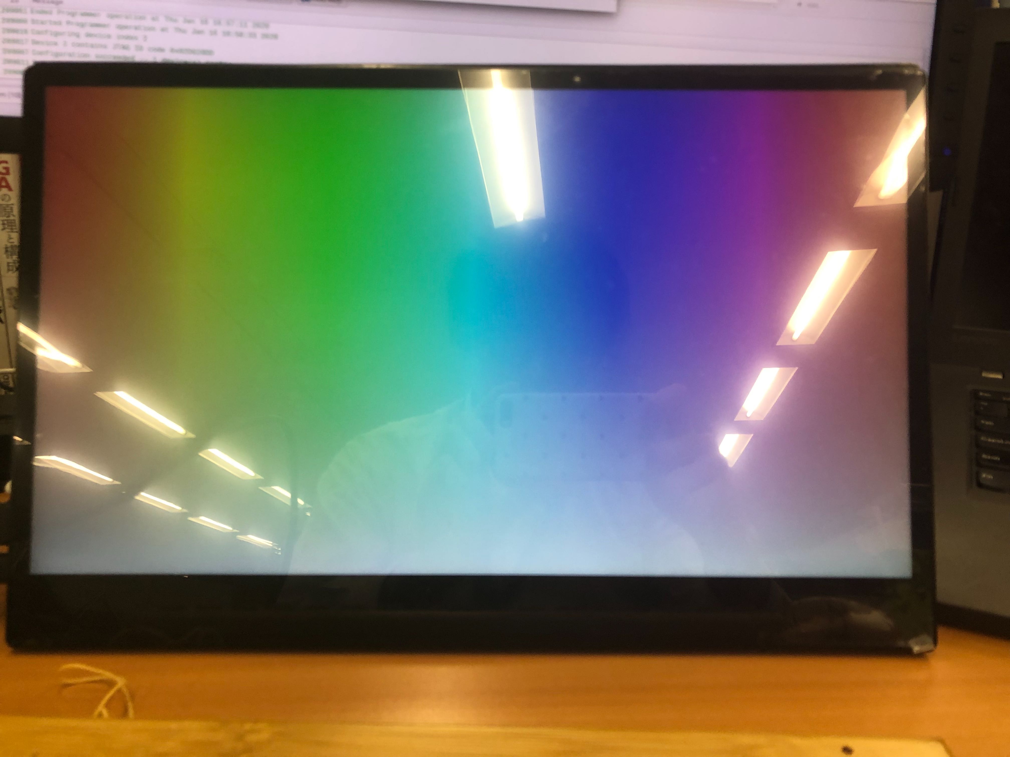
Also, please check the eight LEDs (LED [7: 0]) at the bottom right of the DE10-Nano board. They will start blinking slowly and softly. In the newly configured FPGA design, the eight LEDs are controlled by FPGA PWM circuits, each blinking at slightly different cycles, so the LED blinks gradually sweep and eventually become like random blinks.
As a final check, make sure you have access to the sysid peripheral you added to the overlay file.
Input (on DE10-Nano) :
find /sys -name id | grep fpga
Output
/sys/devices/platform/soc/soc:base-fpga-region/ff201000.sysid/sysid/id
If the SysID peripheral driver has been successfully registered by your overlay, the above file should exist. Take a look at the contents of this file.
Input (on DE10-Nano) :
cat /sys/devices/platform/soc/soc:base-fpga-region/ff201000.sysid/sysid/id
Output
777777777
As the above, if nine "7s" are displayed, it means that the SysID in the FPGA can be read correctly via the driver. Congrats!!!
Section B: Create Device Tree Overlay Container
Step 6: Create a Device Tree Overlay Container
In this step, prepare a container image and a new Azure IoT Edge module in VS Code.
Step 6.1: Add a new module into the VS Code project
Open a command palette in VS Code (Ctrl + Shift + P), type iot edge add, and select Azure IoT Edge: Add IoT Edge Module.

Select deployment.template.json as the setting file to add a new module, C Module as Template Module, and type Module Name, Docker Image Repository in the same step of Module2.
As a sample, they are set as below.
  Module Name: ColorbarOverlayModule
  Docker Image Repository: <your ACR repository address>/colorbar-overlay-module
Step 6.2: Add/Modify files into the module to build a container image
In this step, prepare files to run device tree overlay from a container.
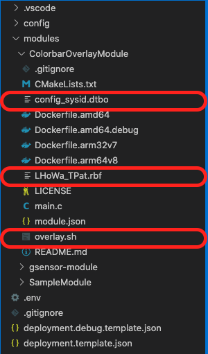
Right Click on ColorbarOverlayModule and New File and type overlay.sh as filename.

This file is an automation script run in a container and the content is here.
#!/bin/bash

overlay_dir="/sys/kernel/config/device-tree/overlays/socfpga"
overlay_dtbo="config_sysid.dtbo"
overlay_rbf="LHoWa_TPat.rbf"

if [ -d $overlay_dir ];then
  echo "Deleting $overlay_dir"
  rmdir $overlay_dir
fi
echo "Copy DTBO and RBF"
cp $overlay_dtbo /lib/firmware/
cp $overlay_rbf /lib/firmware/

echo "creating $overlay_dir"
mkdir $overlay_dir

echo "Doing Device Tree Overlay"
echo config_sysid.dtbo > $overlay_dir/path

echo "Successfully Device Tree Overlay Done."
After creating overlay.sh, right-click the overlay.sh in VS Code and click Open in Integrated Terminal. In the terminal, use chmod to grant privilege.
chmod a+x overlay.sh
Next, copy rbf and dtbo files to the directory. You can the similar strictures.
Then, modify the Dockerfile.arm32v7 to include these files and run the script as CMD.
FROM arm32v7/ubuntu:xenial AS base

WORKDIR /app

COPY overlay.sh /app

COPY LHoWa_TPat.rbf /app
COPY config_sysid.dtbo /app

CMD ["./overlay.sh"]
Step 6.3: Build a container image
Right-click on module.json and Build IoT Edge Module Image and after it is completed successfully, you can check the image from docker image from the integrated terminal.

Note: Make sure your cross-compiling environment is enabled before completing this step. To enable cross-compiling, run the binfmt and inspect commands
Step 7: Local Test of a Device Tree Overlay Container
Once the build is finished, it is recommended to test the image locally at first. For local tests, save, copy this development image to DE10-Nano, and try running it with the docker run command.
This step is the same as Send the Container Image to the DE10-Nano in Module 3.
Open the Development PC's terminal such as integrated terminal in VSCode.
  docker save <your ACR repository address>/colorbar-overlay-module:0.0.1-arm32v7 -o overlay.tar
  scp de10nano-container.tar root@<DE10-Nano IP address>:~/Downloads/
Open a console on the DE10-Nano and load and test the container image.
  docker load -i ~/Downloads/overlay.tar
  docker run --privileged --rm -v /sys/kernel/config:/sys/kernel/config -v /lib/firmware:/lib/firmware <your ACR repository address>/colorbar-overlay-module:0.0.1-arm32v7
Now, this has led to a successful local container test. After that, it only needs to be registered to the ACR and deployed according to the Manifest.
Note: You can skip the local test or upload this development image to the ACR and pull it to test on the DE10-Nano. However, traffic between Azure will increase and the cost may increase. That's why it is recommended that docker saves/loads the image to the share first. You should upload only operational images to the ACR.
Step 8: Run Azure IoT Edge Module
To run this container through Azure IoT Edge, you have to modify only a Manifest. Open the deployment.template.json in VSCode.
This time, you have to update only $edgeAgent:properties.desired:modules as below.
        "modules": {
          "ColorbarOverlayModule": {
            "version": "1.0",
            "type": "docker",
            "status": "running",
            "restartPolicy": "always",
            "settings": {
              "image": "${MODULES.ColorbarOverlayModule}",
              "createOptions": {
                "HostConfig": {
                  "Privileged": true,
                  "Binds": [
                    "/lib/firmware:/lib/firmware",
                    "/sys/kernel/config:/sys/kernel/config"
                  ]
                },
                "Mounts": [
                  {
                    "Type": "bind",
                    "Source": "/lib/firmware",
                    "Destination": "/lib/firmware",
                    "Mode": "",
                    "RW": true,
                    "Propagation": "rprivate"
                  },
                  {
                    "Type": "bind",
                    "Source": "/sys/kernel/config",
                    "Destination": "/sys/kernel/config",
                    "Mode": "",
                    "RW": true,
                    "Propagation": "rprivate"
                  }
                ]
              }
            }
          }
After modifications, run the same flow as Module 3. Right-click on deployment.template.json, select Generate IoT Edge Deployment Manifest, right-click on config/deployment.arm32v7.json, and select Create Deployment for Single Device.
Wait for several minutes while monitoring IoT Edge status and if ColorBar is displayed on the screen, it is a success.
Note: When you check back local container test, make sure iotedge service is stopped because you may encounter issues such as accessing a file at the same time from iotedge modules and local containers. Also, this module will be completed as soon as doing overlay but its setting in Azure IoT Edge is always running. So, it will be re-run and overlay may repeat as well, which means the screen may turn on and off regularly.
Next Steps
You have completed the final tutorial in this four-part series.
Previous module: Create a Container Application that uses the DE10-Nano G-Sensor
Appendix
Device Tree
The device tree is a database file that separates board-specific information (address on the board, operation mode settings, etc.) from the Kernel driver. Even with the same driver code (or kernel binary), different boards can be used only by changing the device tree. It is a Linux mechanism introduced to be able to boot. In fact, by leveraging the Device Tree mechanism, Cyclone® V SoC, Arria® V SoC, and Arria 10 SoC run on the same zImage binary file.
In the device tree file, each device is represented as a node, and the various properties given to each node specify the enable/disable of the device driver, the address, and the operation mode.
The device tree file is read at Kernel startup and used as information (for startup) for the corresponding device driver initialization.
Device Tree overlay
The device tree overlay is a mechanism that allows the contents of the device tree to be rewritten after the kernel is started. This allows you to change the device operating mode and register or delete device drivers while the kernel is running (without the need to restart the kernel).
Devicetree file format (source and binary)
The device tree file that the Kernel can read, also known as the device tree blob, is a binary file. Human-readable and writeable text format files are called device tree sources and use a dedicated tool (device tree compiler = dtc) to generate device tree blob binaries from a textual device tree source. The device tree compiler, which is included in the Kernel build tools, is also included in SoCEDS. (In this tutorial, we use dtc from SoCEDS.) Both device tree and device tree overlay are written in the same format, and both are converted to binary format with dtc. Generally, the extension of the text format file is .dts, and the extension of the binary format is .dtb. In the case of a file for device tree overlay, the extension may be .dtso for text format and .dtbo for binary format.
FPGA region driver
The FPGA region driver is a kernel driver that supports FPGA configuration, operates in cooperation with FPGA Manager and FPGA Bridge drivers, and provides a mechanism for safely reconfiguring FPGA while Linux is running. These three drivers support FPGA configuration: FPGA region driver, FPGA Manager, and FPGA Bridge driver are described in the Linux Documentation as the FPGA Subsystem.
How to configure FPGA via FPGA region driver
Access to the FPGA region driver for FPGA configuration is possible only through the devicetree overlay mechanism. Specifically, to configure with the FPGA bit stream file xxx.rbf, overlay the contents with the property "firmware-name = xxx.rbf" on the FPGA region node, where "xxx.rbf" is the relative path from the /lib/firmware folder.
And, we can add device nodes for peripherals in the FPGA as a child node of the FPGA region node. This makes it possible to configure the FPGA and register the drivers of the device configured in the FPGA at the same time. In addition, if you remove the overlay on the FPGA region node, the child nodes (drivers for the FPGA peripherals) will also be disabled at once. By removing the old overlay from the FPGA region node then performing the new overlay, all the device driver maintenance required to rewrite the FPGA is performed at the same time as the FPGA is configured.
This is the reason for reconfiguring the FPGA using the Devicetree overlay mechanism.
Status of the Linux device tree of the SD card
The status of the Linux device tree booted with the cloud_native SD card image is explained below.
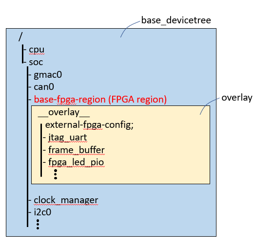
The figure below shows a Devicetree database image on Linux booted with a cloud_native SD card image.
During kernel boot, the device tree is loaded (base_devicetee) and the FPGA region node is spawned under the "/soc" node with the name "base-fpga-region" (full node name is "/soc/base-fpga-region").
Then the shell script (/overlay/fpgaoverlay.sh) launched from the systemd startup service (/etc/systemd/system/fpgaoverlay.service) overlays the base-fpga-region (FPGA region) node. The device tree is in the following state.
The base_devicetree blob loaded during Kernel boot is the soc_system.dtb file in parttion1 on the SD card. Also, the overlay device tree blob loaded by the systemd startup service is /lib/firmware/overlay.dtbo.