Industrial IoT environments commonly use devices that support the Modbus* serial communications protocol, a popular, reliable, and time-tested architecture. These Modbus-compatible devices, instruments, and sensors connect easily via Ethernet or serial cables. Modbus has many variants, including Modbus-RTU protocol, which uses RS-232, RS-422, or RS-485 signaling. This article describes the BIOS settings and connector pinouts required to configure the ports for RS-485, half-duplex mode.
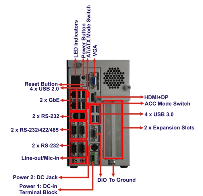
Figure 1. IEI Tank* AIoT Developer Kit Back Panel
The IEI Tank* AIoT Developer Kit has two ports, COM 5 and COM 6, that can be enabled for Modbus serial communications, as indicated by Figure 1.
Modify BIOS Settings
Modifying and saving BIOS settings requires a reboot of the system.
- At system power up, press DEL or F2 to enter the BIOS setup utility. The AMI* BIOS setup utility opens.
- Select the Advanced tab, as shown in Figure 2, and choose F81866 Super IO Configuration. Press Enter.
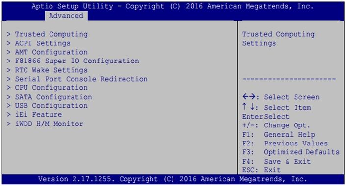
Figure 2. Advanced Tab
- Both serial ports 5 and 6 can be enabled as RS-485. Choose one of these serial ports in F81866 Super IO Configuration, shown in Figure 3, and press Enter.
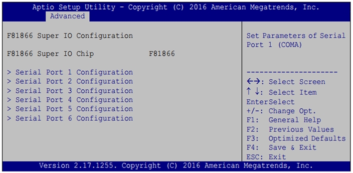
Figure 3. F81866 Super IO Configuration
- Enable the serial port, if not already enabled, which will set the port number and IRQ, as shown in Figure 4. Choose Change Settings.
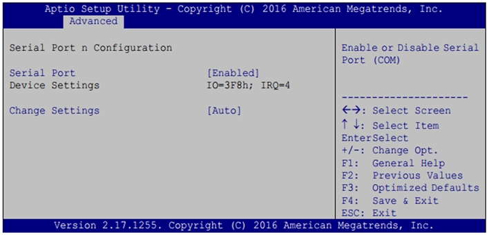
Figure 4. Serial Port n Configuration
- Modify Serial Port Mode by choosing RS485, pictured in Figure 5. Press Enter to choose the serial port mode setting.
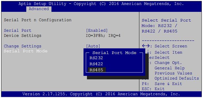
Figure 5. Serial Port Mode
- Figure 6 shows a serial port configured in RS-485 mode. Repeat steps three though five for the other serial port if desired.
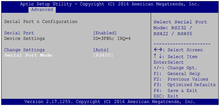
Figure 6. Serial Port Mode RS-485 Chosen
- Press F4 to save settings. The system will reboot.
Configure RS-485 COM Port Wiring
Devices supporting RS-485 use many different methods for describing pin configurations. Some use A and B as signal names while others use +/- notation.
Figure 7 shows three different devices and their notations. For example, the USB serial device on the right indicates that A corresponds to D+ and B corresponds to D-, while device on the left uses a +/- notation.
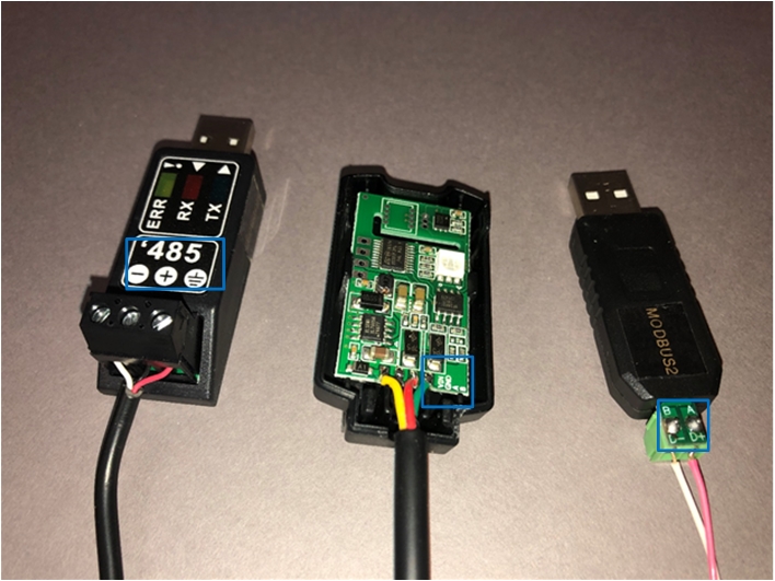
Figure 7. RS-485 Pin Examples
The IEI Tank* AIoT Developer Kit manual supports 2-wire half-duplex RS-485 and uses the notation TX485# and TX485+, as listed in Table 1.
| PIN | RS-485 |
| 1 | TXD485# |
| 2 | TXD485+ |
| 3 | -- |
| 4 | -- |
| 5 | -- |
| 6 | -- |
Table 1. Serial Adapter Pin Configuration for RS-485
Figure 8 is a diagram of a 9-pin serial port adapter wired for RS-485 half-duplex using pins 1 and 2 for the data. Pin 5 is the ground pin. The COM ports on the developer kit are male, requiring a DB-9 adapter. This type of configurable cable does not ship with the IEI Tank* AIoT Developer Kit.

Figure 8. 9-pin Serial Adapter Wired for RS-485 Half-duplex
NOTE: No damage to the kit occurs if pins are connected in the wrong order. If a device is not communicating, swap the data pins as a first step in troubleshooting.
Write to Linux* Device Addresses
The back panel of the IEI Tank* AIoT Developer Kit provides several COM ports, numbered one to six. Linux* device addresses start at zero. When writing applications to send data to COM ports, use the Linux address /dev/ttyS4 for the COM5 physical connector and /dev/ttyS5 for COM6.
