Contents
Intel® Quark™ Microcontroller Developer Kit D2000 Button and LED: Lab Guide.
Step 1: Connect the Intel® Quark™ Microcontroller Developer Kit D2000 board
Step 2: Check the USB driver for the JTAG adapter
Step 3: Run Intel® System Studio™ for Microcontrollers
Step 7: Flash and run the project
Overview
The purpose of this lab is to provide an introduction to the programming of the Intel® Quark™ Microcontroller D2000 using Intel® System Studio 2016 for Microcontrollers. The project used in this lab is a Button and LED sample. This sample demonstrates using D2000 GPIO capabilities, including input, output, and interrupts. The sample uses the on-board user LED and user switch present on the Intel® Quark™ Microcontroller Developer Kit D2000 board. When the switch is pressed, the LED lights up.
Prerequisites
- Host machine:
- PC running Microsoft Windows* 7 or later, with an available USB port
- Software:
- Intel® System Studio for Microcontrollers 2016
- Hardware:
- Intel® Quark™ Microcontroller Developer Kit D2000 board
- USB Type A to Micro USB Type B cable. This cable is supplied with the kit.
Lab Workflow

Lab Instructions
Step 1: Connect the Intel® Quark™ Microcontroller Developer Kit D2000 board
Connect the board to your PC using the USB Type A to Micro USB Type B cable provided in the kit. The green P3V3 LED on the board should light up.
Step 2: Check the USB driver for the JTAG adapter
Open Windows Device Manager. Make sure that you have a USB Serial Port device listed under Ports (COM & LPT) and OpenOCD JTAG device under Universal Serial Bus devices, as shown in the screenshot below.
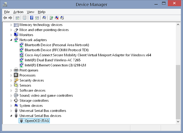
If the OpenOCD JTAG device does not appear or the Universal Serial Bus devices category is missing, the USB driver needs to be installed. To install the driver, navigate to the C:\IntelSWTools\ISSM_2016.0.027\tools\debugger\driver directory using File Explorer, double-click install.bat, and enter Y in the OpenOCD JTAG Driver window that opens.
Step 3: Run Intel® System Studio™ for Microcontrollers
Using File Explorer, navigate to the C:\IntelSWTools\ISSM_2016.0.027 directory, and double-click iss_mcu_ide_eclipse-launcher.bat.
The Intel® System Studio™ for Microcontrollers prompts you to choose your workspace location, as shown below.
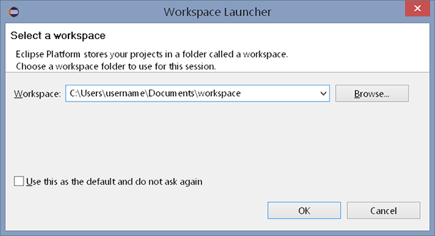
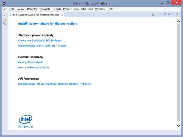
We recommend you click Browse and change the workspace location to your user directory (for example, C:\Users\username\Documents\workspace). Click OK to confirm your changes. The Intel® System Studio for Microcontrollers windows appears as shown in the screenshot below.
Step 4: Update boot ROM
Note: This step needs to be performed only once per board.
From the Intel ISSM menu, select Update target ROM as shown on the screenshot below.
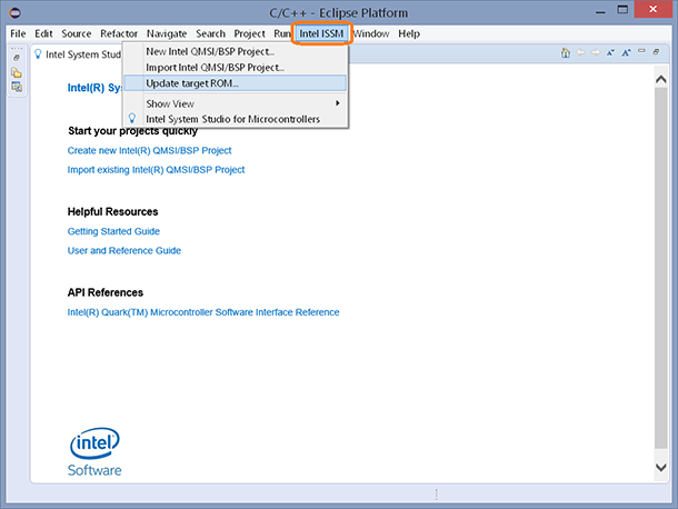
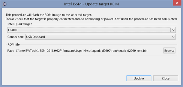
The Update target ROM dialog box appears. Make sure that the selected Intel Quark target is D2000, and the selected Connection is USB Onboard. Click Update to program the ROM to the microcontroller.
Step 5: Create a new project
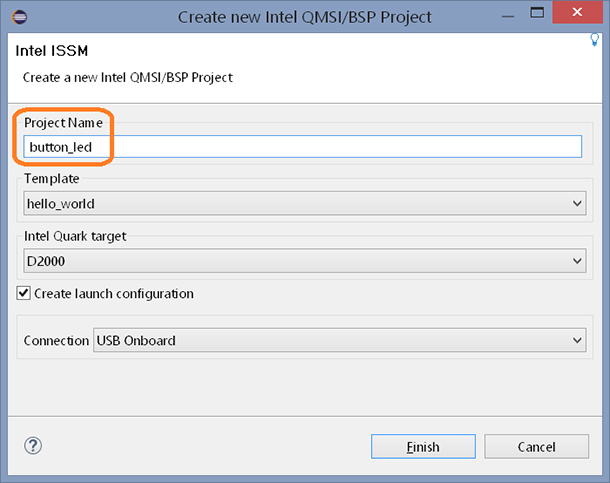
From the Intel ISSM menu, select New Intel QMSI/BSP Project. The Create new Intel QMSI/BSP Project dialog box appears. Type button_led in the Project Name field. Make sure that the other settings match the settings in the screenshot below.
Click Finish to create the new project.
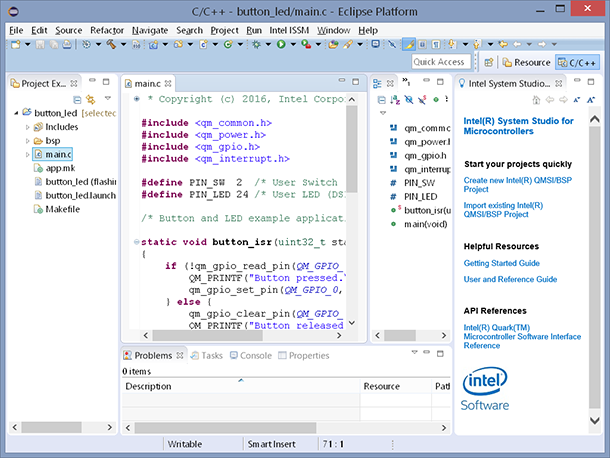
In the Project Explorer window on the left side of Intel® System Studio for Microcontrollers, click the button_led project. Find the main.c file and double-click it to open it the editor. Replace the contents of main.c with the code in the Source Code section below. Save the file by pressing Ctrl-S.
Step 6: Build the project
Click the Build icon ![]() on the toolbar to build the project. Alternatively, you can click the arrow next to the icon and select the build configuration from the menu. Intel® Systems Studio for Microcontrollers provides two configurations: debug and release. The debug configuration includes symbols in the generated binary files to facilitate debugging. It is the default configuration. The release configuration optimizes code for deployment.
on the toolbar to build the project. Alternatively, you can click the arrow next to the icon and select the build configuration from the menu. Intel® Systems Studio for Microcontrollers provides two configurations: debug and release. The debug configuration includes symbols in the generated binary files to facilitate debugging. It is the default configuration. The release configuration optimizes code for deployment.
Step 7: Flash and run the project
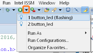
Click the arrow next to the Run icon (the green ‘play’ icon). Select button_led (flashing) from the menu. The Intel® Systems Studio for Microcontrollers will recompile the code and flash it to the microcontroller.
Note: Intel® System Studio for Microcontrollers offers two ways to run the code: The first option, button_led, assumes that the code has already been programmed to the microcontroller. The second option, button_led (flashing), will recompile and re-flash the code. Use this option if the source code has been changed since the last time the microcontroller was programmed. This is the option used in this lab step.
Note: The flashing process takes some time. You can see where you are in the process by looking at the progress bar at the bottom right corner of the Intel® Systems Studio for Microcontrollers window, as shown below.

Step 8: Test the project
Push the user switch SW2, marked as (2) in the picture below. Observe the user LED DS1—marked as (1) in the picture—light up.

Congratulations, you have just completed your first Intel® Quark™ Microcontroller D2000 project!
Step 9: Debug the project
Click the arrow icon next to the Debug icon (the green bug). Select button_led from the menu.
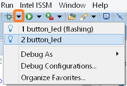
Note: Intel® System Studio for Microcontrollers offers two ways to start debugging. The first option, button_led, assumes that the code has been already programmed to the microcontroller (in this lab, you did this in the “Flashing and running the project” step). The second option, button_led (flashing), will recompile and re-flash the code. Use this option if the source code has been changed since the last time microcontroller was programmed.
Intel® Systems Studio for Microcontrollers displays a Confirm Perspective Switch dialog box to ask you about switching to the Debug perspective. Click Yes.
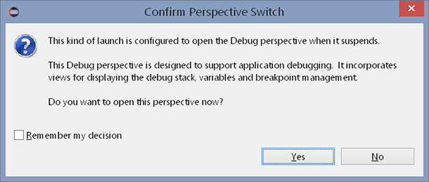
Tip: It is possible to switch between perspectives using the Window -> Open Perspective menu, or by clicking C/C++ or Debug on the Quick Access toolbar, as shown below.

The Debug perspective appears.
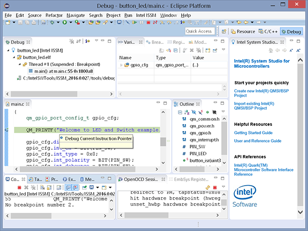
Try using the debug functions described in the following sections.
Toggling breakpoints
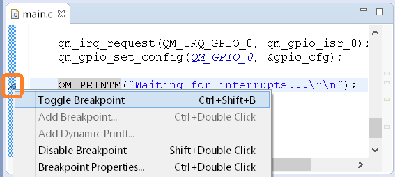
Right-click the bar to the left of the code line where you want to set or remove a breakpoint, and select Toggle Breakpoint from the menu.
Follow the next steps for this lab:
- Find the following line in the file main.c (line 73):
QM_PRINTF("Waiting for interrupts...\r\n"); - Right-click the bar to the left of this line, and select Toggle Breakpoint , as shown in the screenshot below.
Controlling the code execution
You can use the toolbar buttons shown on the screenshot below, their corresponding shortcut keystrokes (for example F5: Step Into, F6: Step Over, F8: Resume), or the commands from the Run menu to control the code execution.
Follow the next steps for this lab:
- Click the Resume icon once. Observe the code running , then stopping at the breakpoint set in the previous step.
- Press the Resume icon again to continue running the code. Test that the code is indeed working by pressing the SW2 switch and observing that the LED lights up.
- Click the Suspend icon to stop the code. Try pressing the SW2 switch again. Did the LED light up?
![]()
These commands are also accessible by right-clicking inside the Debug window.
Adding a conditional breakpoint
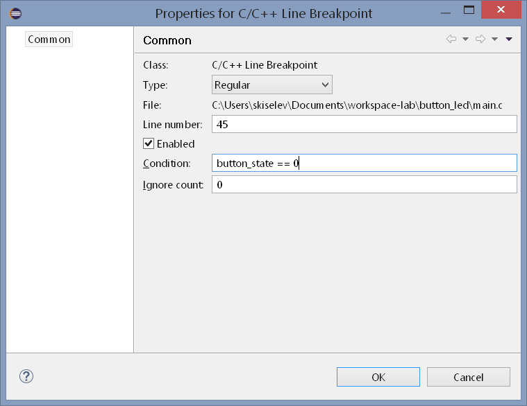
Conditional breakpoints are useful for suspending the code execution when certain conditions are met. Right-click the bar to the left of the code line where you want to add a conditional breakpoint, and select Add Breakpoint. The Properties for C/C++ Line Breakpoint dialog box appears. Enter the condition expression in the Condition text box.
Follow the next steps for this lab:
- Find the following line in the file main.c (line 46):
if (0 == button_state) { - Right-click the bar to the left of this line, and select Add Breakpoint.
- Set the condition to button_state == 0 as shown on the screenshot below, and click OK.
- Click the Resume icon to continue running the code.
- Press the SW2 switch. Observe that the code execution stops at the breakpoint you’ve just added.
Using EmbSys Registers view
The EmbSys Registers view allows viewing and modifying Intel® Quark™ Microcontroller D2000 peripheral registers. This feature is useful when debugging on-chip peripherals and their interaction with the external hardware.
Follow the next steps for this lab:
- Locate the EmbSys Registers window. You might need to enlarge it so that all fields are visible.
- In the EmbSys Registers view, click Peripherals.
- Next, find and click periph_GPIO_reg_i to open the list of GPIO registers.
- Locate the GPIO_SWPORTA_DR register and click it to show the bit fields in this register. This register is the data register for GPIO ports. Bits number 0 to 24 of this register map to the GPIO pins of the microcontroller.
- Double-click the GPIO_SWPORTA_DR again to activate it. The register is displayed in green, and the current value of the register is shown.
- If the current value is not shown, you might need to Resume and Suspend the code.
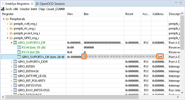
- Click in the Bin value of the GPIO_SWPORTA_DR (bits 24-0) bit field. The buttons for each pin indicating the current bit values and the Set button will appear, as shown on the screenshot below.
- Click on the first bit from the left to change its value to 1. Click Set to send the updated value to the microcontroller. Observe that the LED will light up. This happens because pin 24 is connected to the on-board LED, and setting it to 1 turns on the LED.
- Click on that bit again to change its value back to 0. Click the Set button to send the updated value to the microcontroller. The LED will turn off.
Other debug views
There are multiple other debug views available; feel free to explore them on your own. Here are just some of them:
- Disassembly view
- Registers view
- Memory view
Use Windows -> Show View to select the views. Note that the view selection will vary depending on the active perspective.
OpenOCD view
The Intel® System Studio for Microcontroller uses OpenOCD software to interface to the Intel® Quark™ Microcontroller D2000 through the JTAG interface. This software is running in the OpenOCD view. In some cases, for example when board is disconnected and reconnected, it might be necessary to restart OpenOCD. This can be done by clicking the Stop OpenOCD icon (the red stop sign), and then clicking the Start OpenOCD icon (the green ‘play’ icon) in the top right corner of the OpenOCD view. You must restart the debugging session after OpenOCD has been restarted.
Lab Source Code
The Button and LED sample uses the on-board user switch SW2. This switch is connected to the I/O pin number 2. The code defines and uses the PIN_SW constant to refer to that pin. It also uses the on-board user LED DS2, which is connected to the I/O pin number 24. The code defines and uses the PIN_LED constant to refer to that pin.
The Button and LED sample configures these I/O pins as follows:
- PIN_LED is configured for output mode:
gpio_cfg.direction = BIT(PIN_LED); - PIN_SW is configured for input mode; the respective bit in the gpio_cfg.direction is set to 0.
- The input change interrupt is enabled on the PIN_SW on both rising and falling edges, so that interrupt will be triggered both when the button is pressed and when it is released:
gpio_cfg.int_en = BIT(PIN_SW);
gpio_cfg.int_bothedge = BIT(PIN_SW); - To prevent multiple interrupts due contact bounce, the debounce function is enabled on PIN_SW:
gpio_cfg.int_debounce = BIT(PIN_SW);
The sample sets the button_isr function as the interrupt callback:
gpio_cfg.callback = button_isr;
Next, the sample halts the CPU. The CPU will exit halt mode when an interrupt occurs:
cpu_halt();
On a GPIO interrupt, the button_isr function is called. It reads the input value on the PIN_SW using qm_gpio_read_pin function:
button_state = qm_gpio_read_pin(QM_GPIO_0, PIN_SW);
Then, it sets (outputs logic “1”) or clears (outputs logic “0”) the PIN_LED accordingly, turning on or off the LED:
if (0 == button_state) {
		QM_PRINTF("Button pressed.\r\n");
		qm_gpio_set_pin(QM_GPIO_0, PIN_LED);
	} else {
		QM_PRINTF("Button released.\r\n");
		qm_gpio_clear_pin(QM_GPIO_0, PIN_LED);
/* Button and LED sample */

#include <qm_common.h>
#include <qm_power.h>
#include <qm_gpio.h>
#include <qm_interrupt.h>

#define PIN_SW  2  /* User Switch (SW2) */
#define PIN_LED 24 /* User LED (DS1) */

static void button_isr(uint32_t status)
{
	bool button_state;

	button_state = qm_gpio_read_pin(QM_GPIO_0, PIN_SW);
	/* SW2 has a pull-up: it reads 0 when pressed, and 1 when released */
	if (0 == button_state) {
		QM_PRINTF("Button pressed.\r\n");
		qm_gpio_set_pin(QM_GPIO_0, PIN_LED);
	} else {
		QM_PRINTF("Button released.\r\n");
		qm_gpio_clear_pin(QM_GPIO_0, PIN_LED);
	}
}

int main(void)
{
	qm_gpio_port_config_t gpio_cfg;

	QM_PRINTF("Welcome to LED and Switch example.\r\n");

	/* Configure GPIO pins */
	gpio_cfg.direction = BIT(PIN_LED);
	gpio_cfg.int_en = BIT(PIN_SW);
	gpio_cfg.int_type = 0x0;
	gpio_cfg.int_polarity = BIT(PIN_SW);
	gpio_cfg.int_debounce = BIT(PIN_SW);
	gpio_cfg.int_bothedge = BIT(PIN_SW);
	gpio_cfg.callback = button_isr;

	qm_irq_request(QM_IRQ_GPIO_0, qm_gpio_isr_0);
	qm_gpio_set_config(QM_GPIO_0, &gpio_cfg);

	QM_PRINTF("Waiting for interrupts...\r\n");
	while(1) {
		cpu_halt();
	}

	return 0;
}