Critical Issue
Due to a problem in the R-Tile FPGA IP for Compute Express Link* (CXL*) Design Example User Guide, version 1.10.0, you might observe pof programming failure on DK-DEV-AGI027RBES when following the chapter "C. Programming the Agilex™ 7 FPGA Development Kit with an External USB Blaster II", the description for the programming steps of DK-DEV-AGI027R1BES and DK-DEV-AGI027RBES is not separate and clear enough.
To work around this problem, refer to the following instructions:
1. The programming steps for DK-DEV-AGI027R1BES:
- Connect an external USB blaster II into the J10- External JTAG header.
- Set the switch SW5.3 to ON (for the first time).
- Open the Quartus® Prime Pro Edition Software programmer tool.
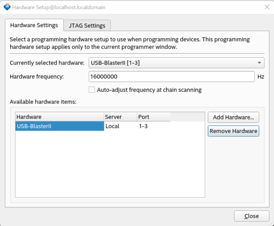
- Click the Hardware Setup, and select USB Blaster II.
- Set the Hardware Frequency to 16000000Hz and uncheck the Auto-adjust frequency at chain scanning box.
- Click Close.

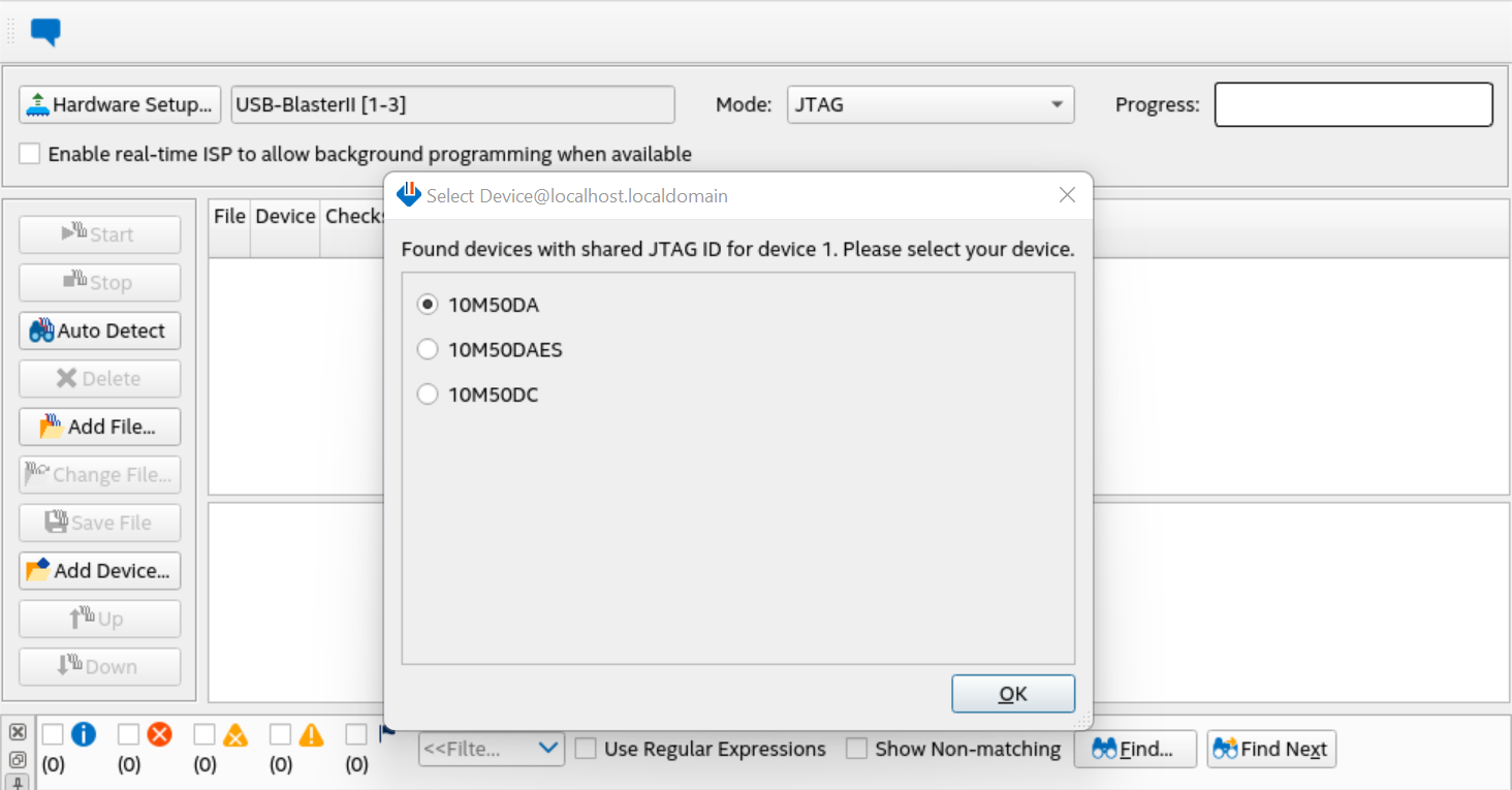
- Click Auto Detect and select MAX® 10 device, click OK.
- Right-click on the MAX® 10 device, and select Edit -> Change File.
- Select the MAX® 10 SOF file image: max10_bmc_avstx8_test.sof and click Open.
- Check the Program/Configure box and click Start to start the programming operation.
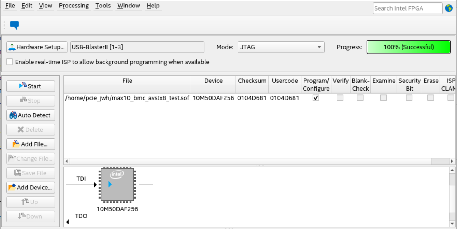
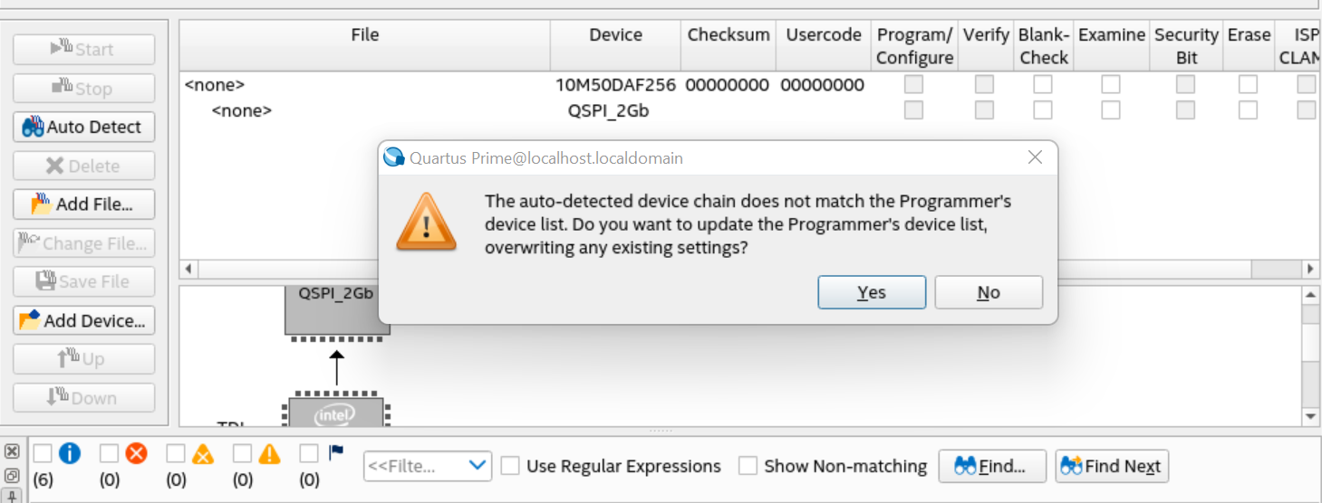
- When the operation is 100% successfully completed, click Auto Detect.
- Click Yes on pop-up windows.
- Right click on the QSPI_2Gb device, select Edit -> Change File.
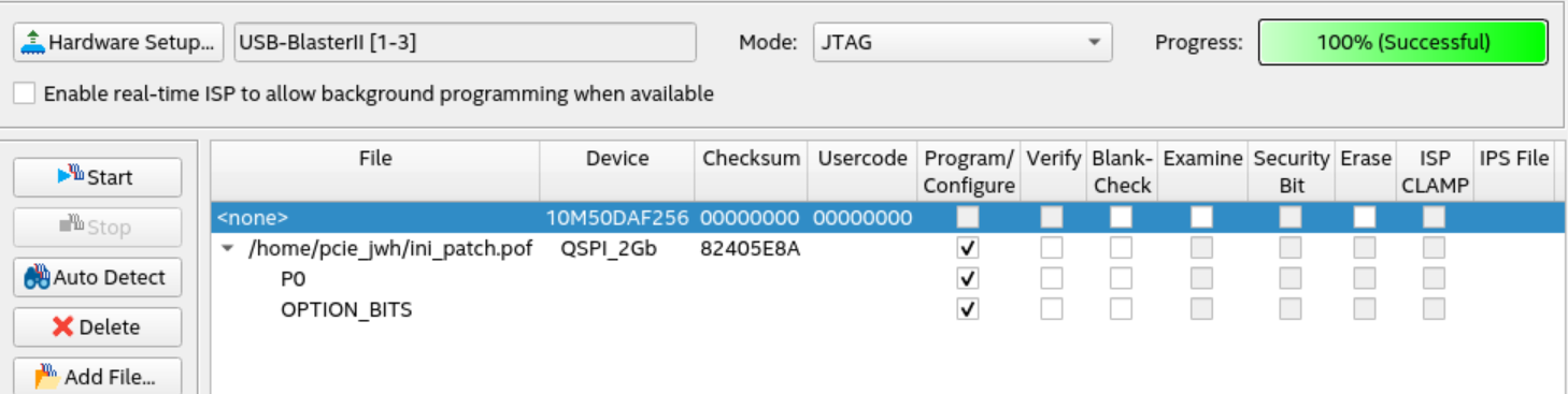
- Select the POF file image: file.pof and click Open.
- Check Program/Configure box of QSPI_2Gb, P1, OPTION_BITS and click Start to start the programming operation.
- When the operation is 100% successfully completed, close the programmer window, shut down the platform (Pressing the on-off button on your server instead of typing “poweroff” in command window), set SW5.3 to OFF, disconnect USB Blaster II and boot the platform again.
- Type “lspci -vt ” in the command window, 0ddb device should be found.
2. The programming steps for DK-DEV-AGI027RBES:
- Plug in the USB cable to the USB port J8 (when using J10, DIPSWITCH SW5.3 (DK-DEV-AGI027RES and DK-DEV-AGI027R1BES) and SW8.3 (DK-DEV-AGI027RB and DK-DEV-AGI027-RA) should be off). Set the DIPSWITCH SW2 to [on:off:off:X] (the 4th bit is don't care). You can follow this combination which has been verified on the hardware:
SW1=ON/Off/Off/Off;
SW2=ON/Off/Off/Off;
SW3=Off/ON/ON/Off;
SW4=Off/Off/ON/Off;
SW5=Off/Off/Off/Off;
SW8=Off/Off/Off/Off
- Open the Quartus® Prime Pro Edition Software programmer tool.
- Click the Hardware Setup, and select USB Blaster II.
- Set the Hardware Frequency to 16000000Hz and uncheck the Auto-adjust frequency at chain scanning box.
- Click Close.
- Click Auto Detect to scan the JTAG devices.
If the JTAG chain can not be detected, try setting SW4:3 to OFF.
If a device called 1_BIT_TAP appears between AGIB027R29AR0 and VTAP10, ignore it and continue to the next step.
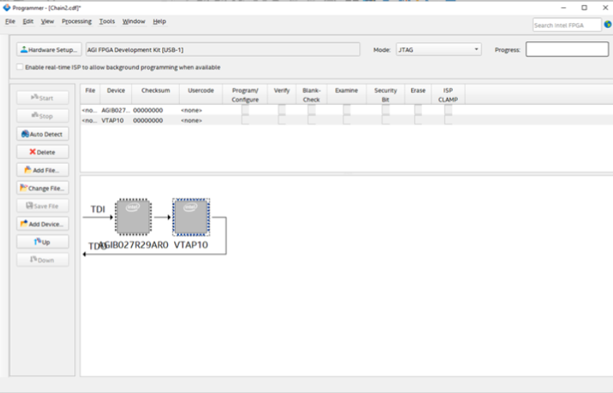
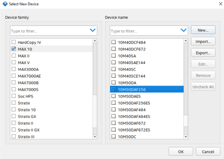
- Right click the VTAP10 device, Edit > Change Device, change it to MAX 10 > 10M50DAF256.
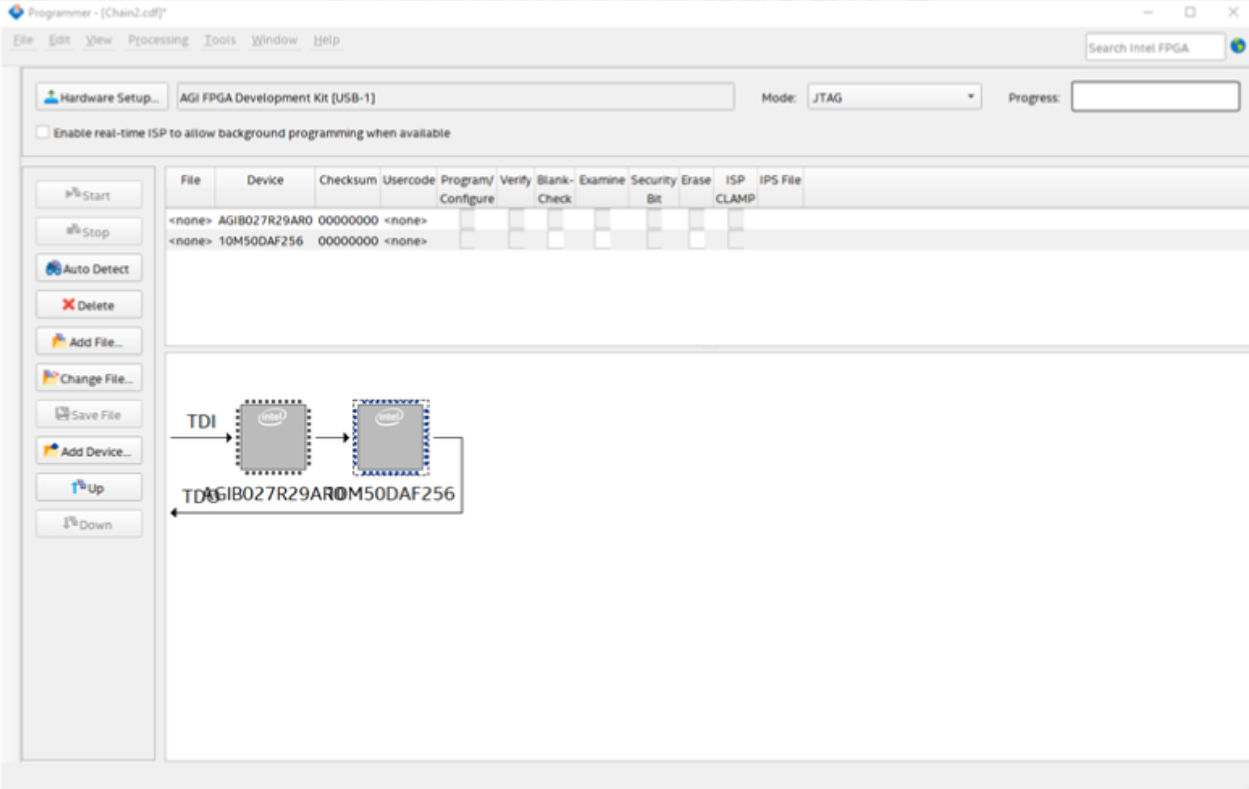
- Right click the 10M50DAF256 device, Edit > Attach Flash Device, select Quad SPI Flash Memory QSPI_2Gb.
- In the Programmer page, click QSPI_2Gb > Change File to select the .pof file.
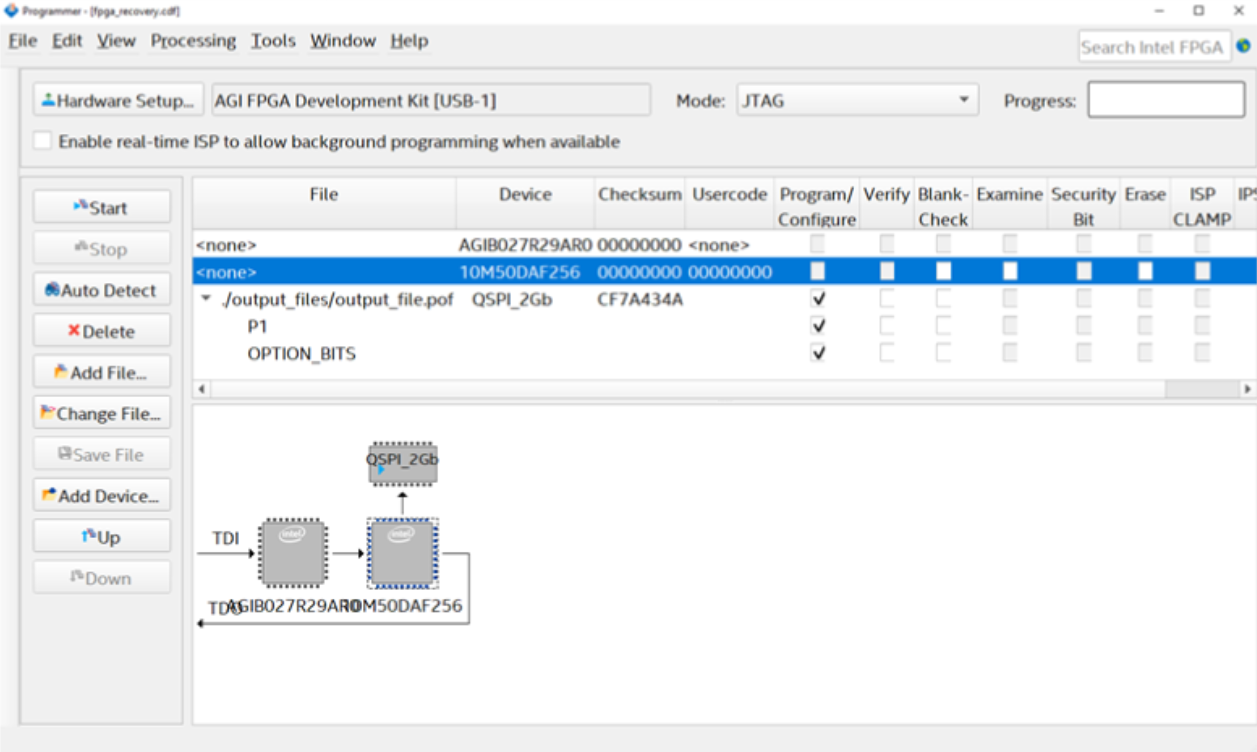
- Start the Programmer.
- When the operation is 100% successfully completed, close the programmer window, and shut down the platform (Pressing the on-off button on your server instead of typing “poweroff” in the command window), if SW4:3 was OFF before, set it to ON, disconnect USB Blaster II and boot the platform again.
- Type “lspci -vt ” in the command window, 0ddb device should be found.