Due to a problem in the Quartus® Prime Pro Edition software version 23.2, designs containing a mixture of 100G, 50G, or 25G PTP and non-PTP ports might cause the Ethernet Subsystem FPGA IP to fail to assert the subsystem_cold_rst_ack_n signal following assertion of the corresponding subsystem_cold_rst_n reset signal.
To determine if your design is affected by this issue, consider the following map of the Agilex™ 7 F-Tile fractures:

The mixture of PTP and non-PTP ports that are affected by this problem is shown below:
CASE – 1
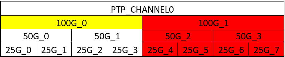
If the 100G_0 fracture is configured as non-PTP and the 100G_1 fracture, or any one of the fractures below 100G_1(highlighted in red), are configured as PTP enabled, the failure will be observed.
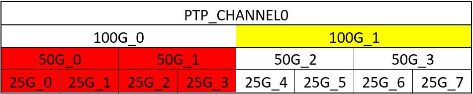
CASE – 2
If the 50G_0 fracture is configured as non-PTP disabled and the 50G_1 or, 50G_2, or 50G_3 fractures, or any one of the fractures below them(highlighted as red), are configured with PTP enabled, the failure will be observed.
CASE-3

If the 50G_1 fracture is configured as non-PTP and the 50G_2 or 50G_3 fractures, or any one of the fractures below them or the 25G_0 or 25G_1 fractures (highlighted as red), are configured with PTP enabled (provided we meet the fracturability requirement of the F-Tile) the failure will be observed.
CASE-4

If the 50G_2 fracture is configured as non-PTP & the 50G_3 fracture, or any one of the fractures below them, or the 25G_0, 25G_1, 25G_2, or 25G_3 fractures (highlighted as red), are configured with PTP enabled, the failure will be observed.
CASE-5
If the 100G_1 fracture is configured as non-PTP and the 50G_0 or 50G_1 fractures, or any one of the fractures below them(highlighted as red), are configured with PTP enabled, the failure will be observed.
CASE-6

If the 50G_3 fracture is configured as non-PTP and the 25G_0, 25G_1, 25G_2, 25G_3, 25G_4, or 25G_5 fractures (highlighted as red) are configured with PTP enabled, the failure will be observed.
CASE-7

If the 100G_2 fracture is configured as non-PTP and the 100G_3 fracture, or any one of the fractures below 100G_3(highlighted in red), are configured with PTP enabled, the failure will be observed.
CASE–8
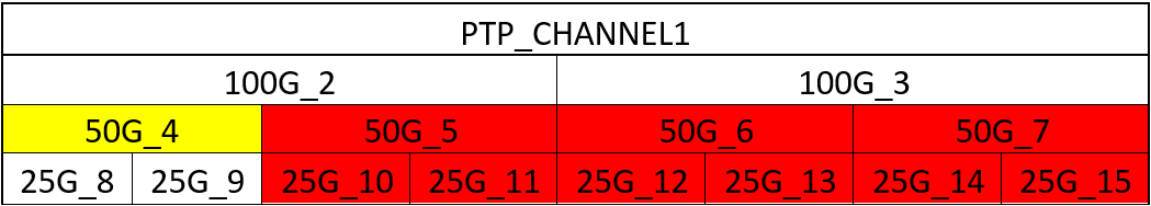
If the 50G_4 fracture is configured as non-PTP and the 50G_5, 50G_6, or 50G_7 fractures, or any one of the fractures below them(highlighted as red), are configured with PTP enabled, the failure will be observed.
CASE-9
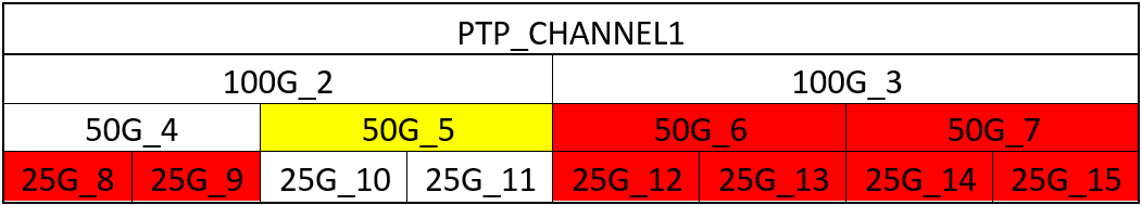
If the 50G_5 fracture is configured as non-PTP and the 50G_6 or 50G_7 fractures, or any one of the fractures below them or the 25G_8 or 25G_9 fractures (highlighted as red), are configured with PTP enabled, the failure will be observed.
CASE-10

If the 100G_3 fracture is configured as non-PTP and the 50G_4 or 50G_1 fractures, or any one of the fractures below them(highlighted as red), are configured with PTP enabled, the failure will be observed.
CASE-11

If the 50G_6 fracture is configured as non-PTP, the 50G_7 fracture, or any one of the fractures below it, or the 25G_8, 25G_9, 25G_10, or 25G_11 fractures (highlighted as red), are configured with PTP enabled, the failure will be observed.
CASE-12

If the 50G_7 fracture is configured as non-PTP and the 25G_8, 25G_9, 25G_10, 25G_11, 25G_12, or 25G_13 fractures (highlighted as red) are configured with PTP enabled, the failure will be observed.
In order to work around this problem in the Quartus® Prime Pro Edition software version 23.2, perform a read-modify-write register access on the AXI-Lite CSR bus to write 3’b000 to data bits [9:7] for specific registers within the F-Tile Ethernet FPGA Hard IP in accordance with the following table:
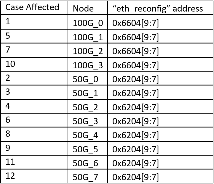
This problem has been fixed in version 24.1 of the Quartus® Prime Pro Edition Software.