1. Measure/predict the amount of differential-mode noise at the receiver end of the cable in worst case conditions. If you have a lot of noise, use a balanced cable like twisted pair which tends to pick up mostly common-mode noise, not differential-mode noise. Do not use simple ribbon cables which can pick up differential-mode noise due to fixed positions of the conductors.
Use a shielded cable if possible. Using a balanced and/or shielded cable is best way to prevent noise problems in noisy environments.
2. Once you have chosen the appropriate cable, measure the amount of differential voltage at the receiver under worst case conditions. Set this equal to VFSB in the equation below and solve for the external failsafe resistors R1 and R3. See both figures linked below.

Figure 1
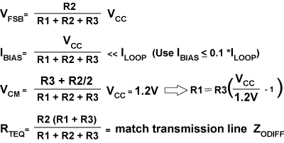
Figure 2
3. You now have an equation relating R1 to R3. Choose R1 and R2 so that: (1) they approximately satisfy the third equation for VCM = 1.2V, and (2) they are large enough that they do not create a bias which will contend with the driver current (IBIAS << ILOOP, equation two). In general, R1 and R2 should be greater than 20k. for VCC = 5V and greater than 12k. for VCC = 3.3V. Remember that you want just enough IBIAS to overcome the differential noise, but not enough to significantly affect signal quality.
4. The external failsafe resistors may change your equivalent termination resistance, RTEQ. Fine tune the value of R2 to match RTEQ to within about 10% of your differential transmission line impedance.