- Remove the two screws securing the bay cover plate to the chassis.
- Unlatch and remove the bay cover plate from the chassis.
- Carefully remove the backplane module from its packaging.
- Position the drive bay module over the power supply bay and slide it back until it is flush with the back of the chassis panel.
- Secure the drive bay module to the chassis using four screws: two on the chassis sidewall, and two on the chassis back panel.
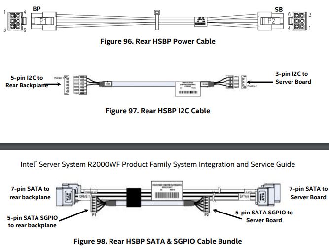
- From the backplane accessory kit, locate the following cables:

- Connect the 2x3 power cable connector (labeled SB) to the server board peripheral PWR connector.
- Connect the 2x3 power cable connector (labeled BP) to the backplane PWR connector.
- Connect the 5-pin I2C cable connector to the matching HSBP_I2C connector on the backplane.
- Connect the 3-pin I2C cable connector to the matching HSBP_I2C connector on the server board.
- Match and connect the 7-pin SATA Drive_0 and Drive_1 cable connectors to the Drive_0 and Drive_1 connectors on the backplane.
- Connect the 5-pin SATA SGPIO cable connector to the SGPIO connector on the backplane.
- Match and connect the 7-pin SATA4 and SATA5 cable connectors to the sSATA4 and sSATA5 connectors on the server board.
- Connect the 5-pin SATA SGPIO cable connector to the SGPIO connector on the server board.
For more information, refer to the 2 x 2.5" Rear Mount Backplane Module Accessory Kit Installation section of the System Integration and Service Guide.
