PCI Express* Configuration in the Intel® Server Board S2600CW Family
Content Type: Product Information & Documentation | Article ID: 000019188 | Last Reviewed: 02/12/2020
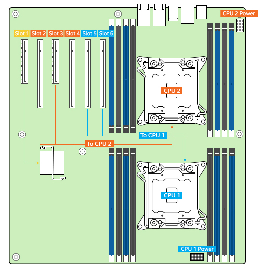
Electrical connections between CPU and PCIe* slots in Intel® Server Board S2600CW2R, S2600CWTR, S2600CW2SR and S2600CWTSR.
From the first processor:
Slot 5: PCIe Gen III x16 connector.
Electrical x16 for S2600CW2R or S2600CWTR
Electrical x8 for S2600CW2SR or S2600CWTSR
Slot 6: PCIe Gen III x16 electrical with x16 physical connector

Single CPU configuration options are shown in the picture below:
| Note | Both CPU power connectors need to be connected in order for all the PCIe slots to work even only one CPU is installed. ** PCIe slot 5 could support 75W cards as long as we do not connect another 75W card on PCIe slot 6 and vice versa. |

Dual CPU configuration options are shown in the picture below:
| Note | Standard PCIe slots can provide up to 25W of power. PCIe slot 2, 4, and 6 can provide up to 75W of power. The higher power requirement needs direct power cables from power supplies. While PCIe slot 5 is also an x16 connector, only 3 x16 PCIe slots on the board can support up to 75W of slot power at a time. This is a configuration limitation based on the System Power budget. When used as riser slot, slot 6 can each provide up to 75W of power to the riser. ** PCIe slot 5 could support 75W cards as long as we do not connect another 75W card on PCIe slot 6 and vice versa. |
