Quick Start Guide—HTML Format for the Intel® Server System SR1600UR
Content Type: Install & Setup | Article ID: 000007524 | Last Reviewed: 08/29/2017
The quick start user's guide for the Intel® Server System SR1600UR provides instructions on how to integrate the processor, memory, and supported accessories. This is a HTML version of the guide. A PDF version is available for download.
Start by reading the safety information for the Intel system. Observe normal ESD precautions when installing add-in card(s).
It is required to use tested processors, memory, and hardware during integration and operation to avoid issues that may occur.
Step 1-4: Preparing your system by removing the cover, riser, air baffle, and heatsink.
Step 5-6: Installing processor and heatsink
Step 7: Installing memory
Step 8-9: Installing optional component, I/O Module, and Intel® Remote Management Module 3 (Intel® RMM3)
Step 10: Installing hard drive for a hot-swap drive system
Step 11: Installing hard drive for a fixed drive system
Step 12: Installing SATA optical device (optional)
Step 13: Installing the air duct
Step 14-15: Installing Add-In card(s) (optional)
Step 16-18: Finishing Up
Step 1: Place your Intel server system on a flat anti-static surface to perform the preceding integration procedures.
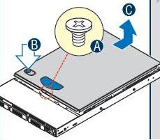
Step 2: Remove the top cover from the chassis by performing the following actions
( A ) remove the security screw
( B ) Depress the latch
( C ) Slide cover back and lift upward
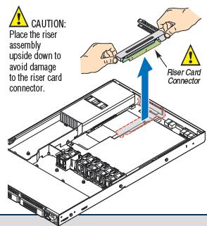
Step 3: Remove Add-in card riser assembly by holding the riser assembly with both hands and lifting it straight up.
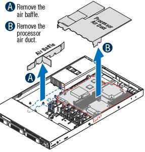
Step 4: Remove ( A ) air baffle, ( B ) processor air duct, heatsink, and spacer prior to installing the processor.
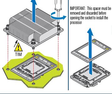
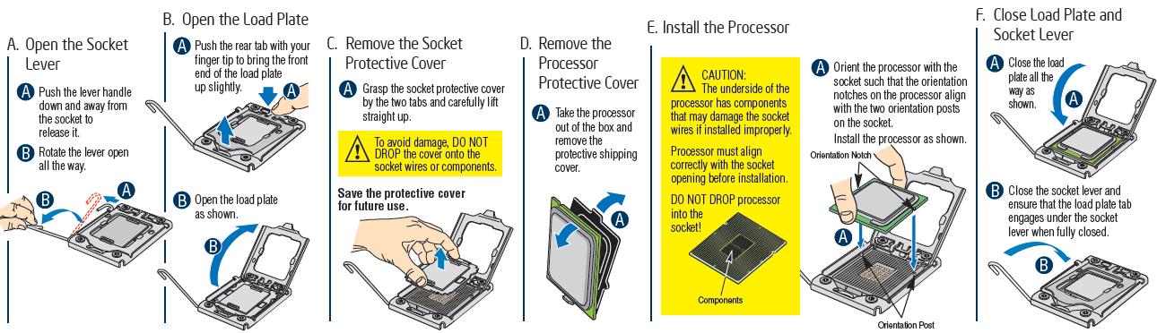
Step 5: Install the processor by following the steps below. This page contains a list of tested processors.
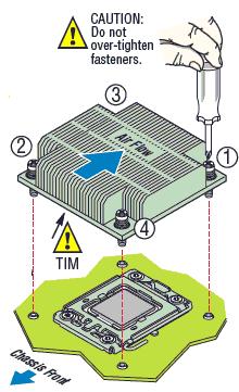
Step 6: Install the heatsink and start with screw #1 as shown on the image moving sequentially. Do not over-tighten the fasteners.
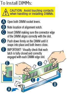
Step 7: Install memory DIMMs. For best performance, a minimum of three DIMMs per CPU is recommended.
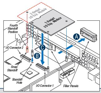
Step 8: Install I/O Expansion Module (optional).
( A ) Squeeze the sides of the filler panel to remove it from the back panel of the chassis. If using a 2-socket I/O expansion module, remove the second filler panel by following the steps stated earlier. If using only a 1-socket IO expansion module, do not remove the second filler panel.
( B ) Install the standoffs as shown in the image below.
( C ) Fit the front of the module into the back panel slot(s), and then attach the module to the server board connector and engage the standoffs.
The Intel® I/O Module hardware specification document provides details about the architecture and feature set of the I/O modules used in the Intel® Server Board or System
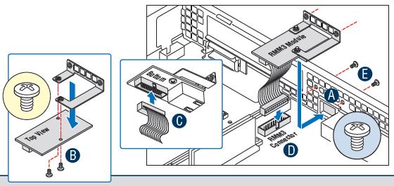
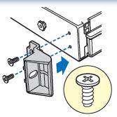
Step 9: Install Intel® Remote Management Module 3 (optional)
( A ) Squeeze the sides of the RMM3 filler panel to remove it from the back panel of the system.
( B ) Attach the RMM3 module bracket to the RMM3 module with two screws as shown in the image below.
( C ) Connect one end of the cable (labeled "RMM3") to the RMM3 connector on the RMM3 module. Cable connectors are keyed and should only go in one way.
( D ) Connect the opposite end of the cable (labeled "server board") to the RMM3 connector on the server board.
( E ) Attach the module bracket to the chassis with 2 screws. The screws install from the back of the chassis.
For additional information on the the Intel® Remote Management Module 3, a user guide and technical product specification are available. To configure the Intel® RMM3 on a supported Intel system, a quick guide is available.
Step 10: Install Hot-swap Drive system components (for a fixed drive system, go to the next step - Step 11)
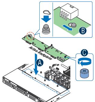
Step 10.1: Install the backplane (Both the active and passive backplane install the same.)
( A ) Position backplane over six chassis standoffs.
( B ) Engage standoffs and slide the backplane to lock it into place.
( C ) Tighten blue thumbscrew.
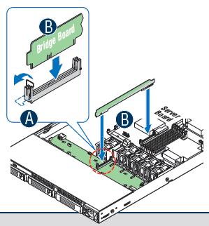
Step 10.2: Install the bridge board
( A ) Open the retention clip located on the backplane.
( B ) Install bridge board, making sure the connector edges on both sides align correctly with the slots. Close the retention clips.
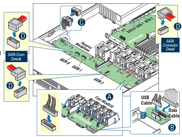
Step 10.3: Make Cable connections
( A ) Route the five-fan module cables over the fan guard and connect to the corresponding connectors on the backplane.
( B ) Connect the USB and data cables from the control panel to the USB and front panel connectors on the backplane.
( C ) Connect the power supply cable to the power connector located on the backplane.
( D ) Passive Backplane Only: Connect the hard drive SATA cables from the server board to the corresponding SATA connectors on the backplane.
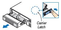
Step 10.4: Install Hot-Swap hard drives (Repeat the steps below for each installed hard drive.)
( A ) Remove hot-swap drive carrier(s) by pushing the green latch towards the lever, opening the lever all the way, and then pulling the drive carrier out of the system.
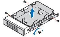
( B ) Remove the plastic air baffle and save for future use.
( C ) Install the hard disk drive and attach with four screws.

( D ) With the carrier lever in the OPEN position, slide drive assembly into chassis until it stops, and then close the lever until it snaps shut.
| Note | If installing less than three drives or devices, empty drive bays must be occupied by carriers with baffles to maintain proper system cooling. Use only carriers that came with your chassis. |
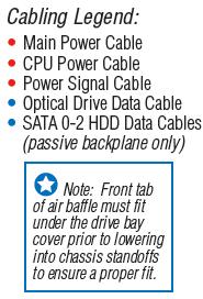
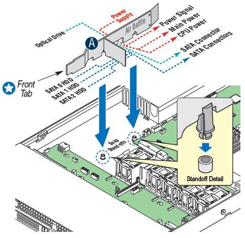
Step 10.5: Install Air Baffle (This is held by two snap-standoffs on the chassis floor.)
( A ) Route all applicable cables through the baffle notches and snap air baffle into place. (Refer to cabling legend below.)
Step 11: Install Hot-swap Drive system components (For a hot-swap drive system, go to the previous step - Step 10.)
Step 11.1: Install Fixed Hard Drives/Carriers (Repeat the steps below for each installed hard drive.)
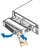
( A ) Remove fixed drive carrier(s) by pressing the blue carrier latch from inside the chassis, pushing the drive carrier forward and sliding it out of the system.
( B ) Remove the plastic air baffle. Save for future use.
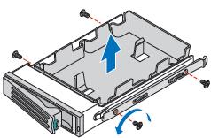
( C ) Install the hard disk drive and attach with four screws.

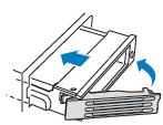
( D ) Slide each carrier into a drive opening until the blue carrier latch clicks into place.

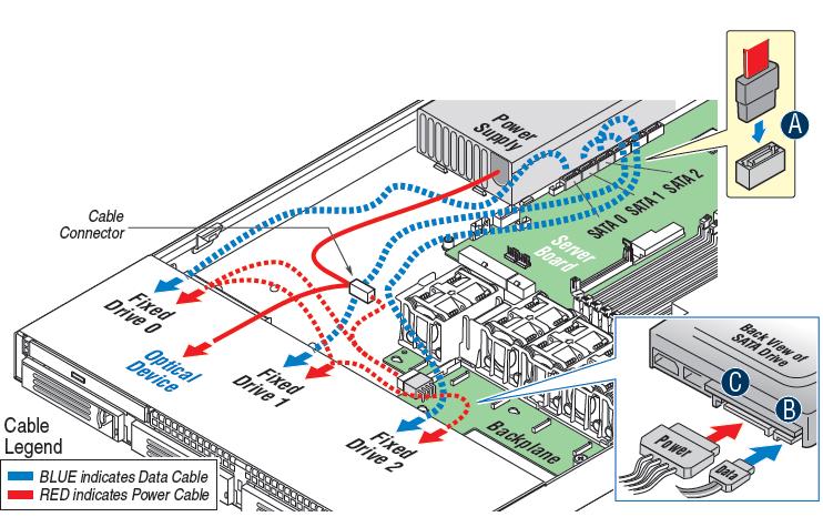
Step 11.2: Install hard drive cables
( A ) Connect SATA data cable(s) to server board.
( B ) Connect opposite end of SATA data cable(s) to hard drive(s).
( C ) Connect the SATA fixed drive power connectors to each hard drive.
Step 11.3: Install Air Baffle (this is held by two snap-standoffs on the chassis floor)
( A ) Route all applicable cables through the baffle notches and snap air baffle into place. (Refer to cabling legend below.)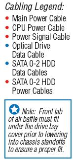
Step 12: Install SATA Optical Device (optional)
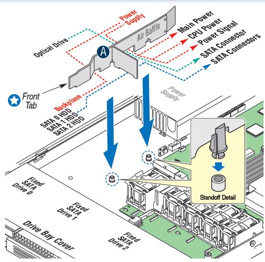
Step 12.1: Remove the empty tray from the accessory kit box
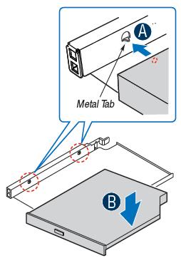
Step 12.2: Install device into the tray
( A ) Align the two holes on the left edge of the optical device with the two metal tabs in the tray.
( B ) Lower opposite side of optical device into the tray until it clicks into place.
Step 12.3: Install optical device tray assembly into the chassis. The power end of the SATA optical device cables comes attached to the midplane board power cable.
( A ) Pull the power and data cables through the front of the chassis opening.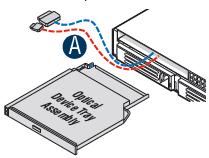
( B ) Connect the cables.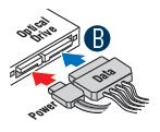
( C ) From the back side of the device bay, pull the cables back into the chassis opening as the device is inserted.
( D ) Verify that the blue release lever on the tray locks into place.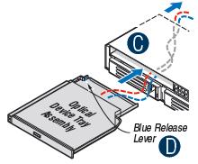
Step 12.4: Install optical device data cable
( A ) Connect the SATA end of the cable to one of the server board SATA connectors.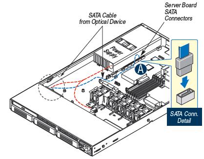
Step 13: Install processor air duct by making sure that the front edge of the duct aligns correctly with the notches on the fan module. Likewise, use care to avoid pinching system cables as it may lead to system instability.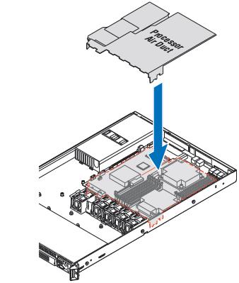
Step 14: Install Add-in card (optional)
( A ) Remove filler panel from the add-in card slot.
( B ) Remove the screw.
( C ) Insert add-in card until it is seated in the riser connector.
( D ) Secure the add-in card with the screw.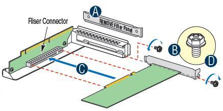
Step 15: Install PCI Add-in card riser assembly
( A ) Position riser card edge connector over the server board riser socket and align the two hooks in the riser with the slots at the back of the chassis.
( B ) Press down uniformly until the two hooks on the rear of the PCI riser assembly engage the chassis back panel slots.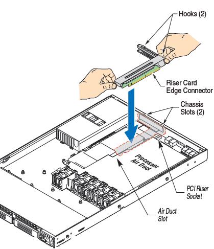
Step 16: Install Rack handles
Step 17: Install top cover by sliding it forward to engage the recessed edge at the front of the cover. Make sure that the latch is locked.Security screw re-installation is optional.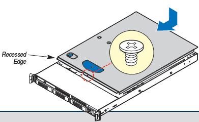
Step 18: Make the necessary I/O connections and plug in AC power. The system must be operated with the top cover installed to ensure proper system cooling.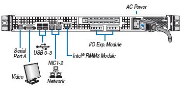
For additional details on how to service the system, refer to the following documentation: