External Memory Interfaces (EMIF) IP User Guide: Agilex™ 3 FPGAs and SoCs
3.5.1. High-level Configuration Tab
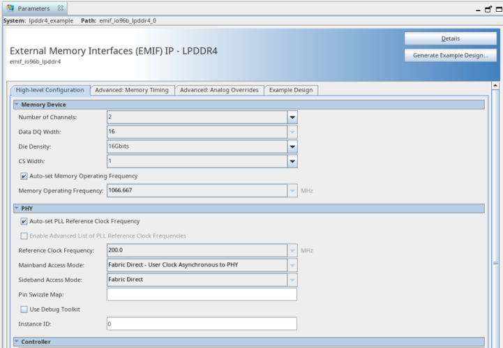
This tab contains three groups of parameters: Memory Device, PHY, and Controller. The tables which follow provide descriptions of the parameters on this tab.
| Parameter Name | Description |
|---|---|
| Number of Channels | Specifies the number of channels that the interface should implement. For multi-channel devices, this should always match the number of channels on the device. Default value is 2 Legal values are: 1, 2 (Identifier: MEM_NUM_CHANNELS) |
| Data DQ Width | Number of DQ pins per memory channel, used for data. Default value is 16 Legal values are: 16, 32 (Identifier: MEM_CHANNEL_DATA_DQ_WIDTH) |
| Die Density | Capacity of each memory die (in Gbits), per channel per die. For dual-die packages, this is the density of each die, not the density of the full package. Default value is 16 Legal values are: 1, 2, 3, 4, 6, 8, 12, 16 (Identifier: MEM_DIE_DENSITY_GBITS) |
| CS Width | Specifies the total number of CS pins used by each channel. Default value is 1 Legal values are: 1, 2 (Identifier: MEM_CHANNEL_CS_WIDTH) |
| Auto-set Memory Operating Frequency | if true, let IP select max frequency that this configuration can support for the current device speedgrade. If false, user can set custom value for operating frequency. Default value is true (Identifier: MEM_OPERATING_FREQ_MHZ_AUTOSET_EN) |
| Memory Operating Frequency | Specifies the frequency at which the memory interface will run. Legal values are: 800, 1066.667. (Identifier: MEM_OPERATING_FREQ_MHZ) |
| Parameter Name | Description |
|---|---|
| Auto-set PLL Reference Clock Frequency | if true, let IP select max PLL refclk frequency that this configuration can support. If false, user can set custom value for PLL refclk frequency. Default value is true (Identifier: PHY_REFCLK_FREQ_MHZ_AUTOSET_EN) |
| Enable Advanced List of PLL Reference Clock Frequencies | If true, provide extended list of possible refclk values. Otherwise, prune possible list of refclk values to a more reasonable length. Default value is false (Identifier: PHY_REFCLK_ADVANCED_SELECT_EN) |
| Reference Clock Frequency | Specifies the reference clock frequency for the EMIF IOPLL. (Identifier: PHY_REFCLK_FREQ_MHZ) |
| AC Placement | Indicates location on the device where the interface will reside (specifically, the location of the AC lanes in terms I/O BANK and TOP vs BOT part of the I/O BANK). Legal ranges are derived from device floorplan. Default value is BOT Legal values are: BOT, TOP, FULL (Identifier: PHY_AC_PLACEMENT) |
| Auto-set Mainband Access Mode | if true, let IP select most likely usecase for the PHY_MAINBAND_ACCESS_MODE; if false, let user set a custom value for sideband access mode. Default value is true (Identifier: PHY_MAINBAND_ACCESS_MODE_AUTOSET_EN) |
| Mainband Access Mode | Specifies the path through which the EMIF QHIP mainband interface is exposed to the user. The mainband interface is the AXI4 interface to the memory controller. Legal values are: ASYNC, SYNC (Identifier: PHY_MAINBAND_ACCESS_MODE) |
| Auto-set Sideband Access Mode | if true, let IP select most likely usecase for the PHY_SIDEBAND_ACCESS_MODE; if false, let user set a custom value for sideband access mode. Default value is true (Identifier: PHY_SIDEBAND_ACCESS_MODE_AUTOSET_EN) |
| Sideband Access Mode | Specifies the path through which the EMIF QHIP sideband interface is exposed to the user. The sideband interface is the AXI4-Lite interface to the IOSSM. Legal values are: FABRIC. (Identifier: PHY_SIDEBAND_ACCESS_MODE) |
| Pin Swizzle Map | Specifies the swizzle map for the data lanes and pins. (Identifier: PHY_SWIZZLE_MAP) |
| Use Debug Toolkit | If enabled, the AXI-L port will be connected to SLD nodes, allowing for a system-console avalon manager interface to interact with this AXI-L subordinate interface. Default value is false (Identifier: DEBUG_TOOLS_EN) |
| Instance ID | Instance ID of the EMIF IP. This is useful when using a discovery mechanism over the side-band interface, to identify which EMIF instance's mailbox is at which offset. If expecting to use a discovery mechanism in hardware, this parameter must be set uniquely for all EMIFs that share a sideband. Otherwise, this parameter can be ignored / kept at the default value. Default value is 0 Legal values are: from 0 to 6 (Identifier: INSTANCE_ID) |
| Parameter Name | Description |
|---|---|
| Use In-Line ECC | Specifies whether in-line ECC is enabled in the controller. When in-line ECC is enabled, the available memory capacity is reduced by one-eighth to store the ECC checkbits. The maximum AXI address is reduced by the same amount. Default value is false (Identifier: CTRL_ECC_INLINE_EN) |
| Use ECC Autocorrection | If ECC is enabled, specifies whether single-bit-errors (SBEs) should be corrected or just reported. Default value is true (Identifier: CTRL_ECC_AUTOCORRECT_EN) |
| Use Data Masking | Specifies whether Data Masking is enabled by the controller. RMW will occur under these conditions: AXI transactions using a subset of write strobe, or one beat long AXI transaction in DDR5, LPDDR5, or LPDDR4 interfaces. Altera recommends enabling the DM option to improve efficiency for the following cases: non-ECC design with AXI transaction listed above, and LPDDR4 or LPDDR5 designs with In-Line ECC enabled. Default value is false (Identifier: CTRL_DM_EN) |
| Use WDBI | Specifies whether write Data-bus-inversion is enabled by the controller. Default value is false (Identifier: CTRL_WR_DBI_EN) |
| Use RDBI | Specifies whether read Data-bus-inversion is enabled by the controller. Default value is false (Identifier: CTRL_RD_DBI_EN) |