Quartus® Prime Pro Edition User Guide: Timing Analyzer
ID
683243
Date
12/04/2025
Public
1.1.1. Timing Path and Clock Analysis
1.1.2. Clock Setup Analysis
1.1.3. Clock Hold Analysis
1.1.4. Recovery and Removal Analysis
1.1.5. Multicycle Path Analysis
1.1.6. Metastability Analysis
1.1.7. Timing Pessimism
1.1.8. Clock-As-Data Analysis
1.1.9. Multicorner Timing Analysis
1.1.10. Time Borrowing
2.1. Using Timing Constraints throughout the Design Flow
2.2. Timing Analysis Flow
2.3. Applying Timing Constraints
2.4. Timing Constraint Descriptions
2.5. Timing Report Descriptions
2.6. Scripting Timing Analysis
2.7. Using the Quartus® Prime Timing Analyzer Document Revision History
2.8. Quartus® Prime Pro Edition User Guide: Timing Analyzer Archive
2.4.4.5.1. Default Multicycle Analysis
2.4.4.5.2. End Multicycle Setup = 2 and End Multicycle Hold = 0
2.4.4.5.3. End Multicycle Setup = 2 and End Multicycle Hold = 1
2.4.4.5.4. Same Frequency Clocks with Destination Clock Offset
2.4.4.5.5. Destination Clock Frequency is a Multiple of the Source Clock Frequency
2.4.4.5.6. Destination Clock Frequency is a Multiple of the Source Clock Frequency with an Offset
2.4.4.5.7. Source Clock Frequency is a Multiple of the Destination Clock Frequency
2.4.4.5.8. Source Clock Frequency is a Multiple of the Destination Clock Frequency with an Offset
2.5.1. Report Fmax Summary
2.5.2. Report Timing
2.5.3. Report Timing By Source Files
2.5.4. Report Data Delay
2.5.5. Report Net Delay
2.5.6. Report Clocks and Clock Network
2.5.7. Report Clock Transfers
2.5.8. Report Metastability
2.5.9. Report CDC Viewer
2.5.10. Report Asynchronous CDC
2.5.11. Report Logic Depth
2.5.12. Report Neighbor Paths
2.5.13. Report Register Spread
2.5.14. Report Route Net of Interest
2.5.15. Report Retiming Restrictions
2.5.16. Report Register Statistics
2.5.17. Report Pipelining Information
2.5.18. Report Time Borrowing Data
2.5.19. Report Exceptions and Exceptions Reachability
2.5.20. Report Bottlenecks
2.5.21. Check Timing
2.5.22. Report SDC
2.5.23. Design Closure Summary
3.1.1. CDC Timing Overview
3.1.2. Identifying CDC Timing Issues Using Design Assistant
3.1.3. Identifying CDC Timing Issues Using Timing Reports
3.1.4. Debug CDC Example 1—Incorrect SDC Definition
3.1.5. Debug CDC Example 2—Additional Logic in the Crossing
3.1.6. Debug CDC Example 3—CDC Depending on Two Simultaneous Clock Domains
2.4.4.5.1. Default Multicycle Analysis
By default, the Timing Analyzer performs a single-cycle analysis to determine the setup and hold checks. Also, by default, the Timing Analyzer sets the end multicycle setup assignment value to one and the end multicycle hold assignment value to zero.
The source and the destination timing waveform for the source register and destination register, respectively where HC1 and HC2 are hold checks 1 and 2 and SC is the setup check.
Figure 102. Default Timing DiagramThe timing waveforms show the source and destination registers of a data transfer. HC1 and HC2 are the hold checks that Timing Analyzer performs. SC is the setup check that Timing Analyzer performs.
Figure 103. Setup Check Calculation
The most restrictive default single-cycle setup relationship, with an implied end multicycle setup assignment of one, is 10 ns.
Figure 104. Default Setup Report
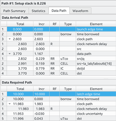
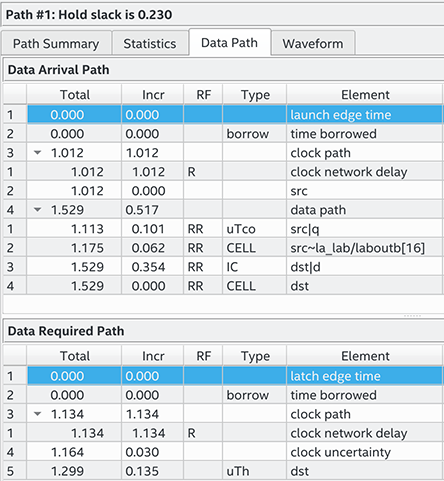
Figure 105. Hold Check CalculationThe figure shows the hold timing report with the launch and latch edge times highlighted.
The most restrictive default single-cycle hold relationship, with an implied end multicycle hold assignment of zero, is 0ns.
Figure 106. Default Hold Report The figure shows the hold timing report with the launch and latch edge times highlighted.