This technical documentation expands on the information in L1 Terminal Fault Software Guidance. Be sure to review the overview and mitigation for software developers, and be sure to apply any microcode updates from your OS vendor. For more information, refer to the list of affected processors.
How L1TF Works
When the processor accesses a linear address, it first looks for a translation to a physical address in the translation lookaside buffer (TLB). For an unmapped address this will not provide a physical address, so the processor performs a “table walk”1 of a hierarchical paging structure in memory that provides translations from linear to physical addresses. A page fault is signaled if this table walk fails.
A paging structure entry is vulnerable to an L1TF exploit when it is not Present(P=0) or when it has a reserved bit set2. A fault delivered for either of these entries is a terminal fault because the condition causes the address translation process to be terminated immediately, without completing the translation. Although access is denied, speculative execution may still occur.
During the process of a terminal fault, the processor speculatively computes a physical address from the paging structure entry and the address of the fault. This physical address is composed of the address of the page frame and low order bits from the linear address. If data with this physical address is present in the L1D, that data may be loaded and forwarded to dependent instructions. These dependent instructions may create a side channel.
Because the resulting probed physical address is not a true translation of the virtual address, the resulting address is not constrained by various memory range checks or nested translations. Specifically:
- Intel® Software Guard Extensions (Intel® SGX) protected memory checks are not applied.
- Extended Page Table (EPT) guest physical to host physical address translation is not applied.
- SMM protected memory checks are not applied.
Details and Example of L1TF Address Calculation
The physical address used to search the L1D is dependent on the level of the paging structures where the fault occurred and the contents of the paging structures. If the table walk completes at a level of the paging structure hierarchy with the page size(PS)bit set, the addresses used to read the L1D consumes different bits from the linear address and page frame depending on the level.
Table 1. Address Calculation
| Vulnerable paging structure entries | Bits from paging structure entry | Bits from faulting address | Amount of physical memory |
|---|---|---|---|
| PTE, or any paging structure entry with PS=0 | M-1:12 | 11:0 | 4 KB |
| PDE with PS=1 | M-1:21 | 20:0 | 2 MB |
| PDPTE with PS=1 | M-1:30 | 29:0 | 1 GB |
| PML43 | M-1:12 | 11:0 | 4 KB |
An example that could lead to L1TF is when a read-only paging structure entry referring to physical page 0x1000 is changed to be inaccessible because the page is being swapped out.
Original entry: 0x1001 (P=1)
The operating system (OS) makes the page not accessible by clearing the Present (P) bit:
New entry (vulnerable): 0x1000 (P=0)
This vulnerable entry might be used by an L1TF exploit to infer the contents of physical page 0x1000 if the contents of the page were present in the L1D. Refer to the Mitigating Unmapped Paging Structure Entries section below for mitigation options in this scenario.
How Enclave to Enclave (E2E) Works
The enclave-to-enclave (E2E) method is a subvariant of the L1TF method. E2E may expose memory in one Intel SGX enclave to software that is running in a different Intel SGX enclave on the same core.
When code running inside an Intel SGX enclave accesses a linear address in ELRANGE4, the processor translates the address using normal translation mechanisms. The processor verifies that the physical address refers to a page within the protected Enclave Page Cache (EPC). The processor then checks the Enclave Page Cache Map (EPCM) to ensure that this enclave is allowed to access this physical address. Among other checks, this determines whether the page is valid and accessible by this particular enclave.
If the EPCM check indicates an access violation, the operation will not be allowed to architecturally complete and typically results in a page fault. However, if the forbidden access is a load and the physical address is present in the L1D, the actual data may be observed by speculative dependent operations.
If a physical page belonging to an Intel SGX enclave is mapped into the ELRANGE of another enclave, the second enclave could infer data in that page using E2E. As E2E is a subset of L1TF, only lines present in the L1D may be exposed by E2E. Unlike L1TF, the E2E probe can happen speculatively before previous instructions have been resolved.
L1TF Limiting Factors
L1TF can only be exploited by code running on a physical core that has secrets in its L1D. Secrets can be anything that should not be known by other code modules, processes, users, etc. Systems that do not run untrusted code are not affected.
An L1TF exploit is composed of three elements. All three elements are required for an exploit to be successful.
- Secret data must be present in the L1D of a processor’s physical core. Data in the L1D is frequently replaced, so the window of opportunity for the attacker might be small.
- Malicious code is executed on the same physical core as the victim’s data. The malicious code must directly create (in a virtual machine) or indirectly create (via manipulating the bare-metal host OS) a paging structure entry that, if valid, would point to the physical address of a page containing a secret.
- Malicious code exploits the paging structure entry to speculatively access data in the L1D and infer its contents using a speculative execution side-channel method.
In element 1, secret data is loaded into the L1D of a processor's physical core as the victim accesses the data (either directly or speculatively). In elements 2 and 3, the attacker must locally run malicious code on the same physical core as the victim's data.
Affected Hardware
See the Appendix: List of Affected Processors section.
Processors that have the RDCL_NO bit set to one (1) in the IA32_ARCH_CAPABILITIES MSR are not susceptible to the L1TF speculative execution side channel. On such processors, none of the following mitigations are required.
Processors that implement Intel® HT Technology5 share the L1D between all logical processors (hyperthreads) on the same physical core. This means that data loaded into the L1D by one logical processor may be speculatively accessed by code running on another logical processor. Processors that implement Intel HT Technology require additional mitigations described in the Appendix: Intel® Hyper-Threading Technology section as well as the mitigations described in the Virtual Machine Monitors (VMMs) section. Disabling hyperthreading does not in itself provide mitigation for L1TF.
Mitigation by Removing Secrets from L1D
Data that might be leaked by an L1TF exploit must be present in the L1D while malicious code executes. When transitioning to less-privileged code, removing data from the L1D mitigates exploits that might be launched in the less-privileged code.
Traditional architectural cache-flushing operations, such as WBINVD and the CLFLUSH family, can be used to remove secrets from the L1D, but these solutions flush data from all cache levels of the local processor. The IA32_FLUSH_CMD MSR is more precise and does not flush higher cache levels, thereby limiting its impact only to the L1 cache on the physical core executing the flush itself.
While these mechanisms provide mitigation to keep data out of the L1D, data prefetchers and speculative execution may reload data that has been removed. To mitigate against data being reloaded, minimize or eliminate periods after a L1D cache flush where secret data is both mapped in and is marked as cacheable. For example, a VMM could use the MSR load list to trigger IA32_FLUSH_CMD as part of VM entry.
Specific mitigations for various operating environments are described below.
Mitigations Preventing Data from Being Loaded Into L1D
Software can prevent data from being reloaded into the L1D after a flush by removing cacheable mappings of that data.
For instance, to prevent secret data from being loaded into the L1D via a paging structure entry, software could clear the Present bit of the entry and flush the paging structure caches followed by flushing the L1D. An alternative to clearing the Present bit would be using uncacheable memory types specified via the Page Attribute Table (PAT) or Memory Type Range Registers (MTRRs), both of which also prevent data from being loaded in the L1D.
Further cache flushing operations are not required for mitigation after these entries have been put in place.
Mitigating Operating Systems (OS)
Whether the OS is running on bare-metal or as a virtual machine, the OS is responsible for mitigating against exploitation of paging structure entries (PTEs) by malicious applications. To do this, the OS can ensure that vulnerable PTEs refer only to specifically-selected physical addresses, such as those addresses outside of available cached memory or addresses that do not contain secrets.
There are four typical cases that need mitigation in an OS:
- Pages with no valid mappings.
- Pages that have been written to other storage (swapped out), such as when the OS is short of memory.
- Pages where the application has requested that the OS disable access.
- Pages in transitional states where the OS needs to temporarily block access.
In the first case, OSes may use an all-zero paging structure entry to represent linear addresses with no physical mapping (including the Page Size Extension (PSE) bit7 where supported) while ensuring that the 4 KB page frame starting at physical address 0 contains no secrets.
For the other three cases, the OS should make the PTEs refer to invalid memory addresses, as described in the following sections.
Mitigation by Referring to Addresses Free of Secrets
If a vulnerable paging structure entry (for example, an entry that is not present or has a reserved bit set) sets its page frame to refer to a region with no secret data, then an attack on that entry will not reveal secret data.
An example of this is to have the vulnerable paging structure entry point to physical address 0 (with PS cleared) and to have 4 KB of zero data at physical address 0. The bare-metal OS and VMM need to maintain the effectiveness of this strategy by never keeping secret data at that physical address. Due to this, we suggest using 4 KB of zero data at physical address 0 as a convention.
At the page directory entry (PDE) and page directory pointer table entry (PDPTE) levels, paging structures marked as not present should ensure the PS bit is zero (PS=0) to avoid making 2 MB or 1 GB of physical memory vulnerable.
Mitigation by Referring to Invalid Memory
Many OSes store metadata in non-present paging structure entries to assist in operations such as paging. These entries may be meant to direct the OS to the location that data has moved to on disc. Using the L1TF side channel method this metadata may instead be used to point to a memory location in L1D, which would expose whatever data is at that location. An OS can mitigate L1TF exploits against these entries by ensuring that this metadata only refers to invalid addresses, meaning addresses that would not point towards data in the L1D. While there are many possible methods to construct invalid addresses, the approach described here constructs invalid addresses while preserving space for metadata.
An OS can construct a mitigated paging structure entry by having the entry refer to a physical memory address that is below the address represented by MAXPHYADDR8, but above the highest cacheable memory on the system that might contain secrets. For instance, an OS can set the MAXPHYADDR-1 bit in the PTE and ensure that no cacheable memory containing secrets is present in that top half of the physical address space.
This approach effectively repurposes part of the physical address space, which may impact the maximum usable memory on the system. An OS may dedicate more than one bit for this functionality expanding the usable physical address space. For example, the OS may set the top two bits so that only the top quarter of the physical address space cannot be used for cacheable accesses. Note that, as it dedicates more bits, the OS may lose capacity to store metadata in the paging structure entry.
The OS may also set the bits from MAXPHYADDR through 51 in the PTE. This adds mitigation in the case where a virtualized MAXPHYADDR differs from the platform, bare-metal value.
For the example of PTE pointing to page 0x1000 in the How L1TF Works section, this would be:
Original entry: 0x1001 (P=1)
The OS wants to make the page not accessible and clears the P bit
New entry (vulnerable): 0x1000 (P=0)
The CPU reports MAXPHYADDR as 36. To mitigate an L1TF exploit on this vulnerable entry, an OS can set bits 35 to 51 inclusive in the entry to ensure that it does not refer to any lines in the L1D. This assumes that the system does not use any memory at an address with bit 35 set.
New entry (mitigated): 0x000ffff800001000 (P=0)
When the OS wants to make the page accessible again, it can set the P bit again and clear the extra set bits:
Entry present again: 0x1001 (P=1)
Some processors may internally implement more address bits in the L1D cache than are reported in MAXPHYADDR. This is not reported by CPUID, so the following table can be used:
Table 2: Processors Implementing More L1D Address Bits than Reported
| Processor code name | Implemented L1D bits |
|---|---|
| Nehalem, Westmere | 44 |
| Sandy Bridge and newer | 46 |
On these systems the OS can set one or more bits above MAXPHYADDR but below the L1D limit to ensure that the PTE does not reference any physical memory address. This can often be used to avoid limiting the amount of usable physical memory.
Mitigation by Referring to Uncacheable Memory
Since data is only vulnerable to an L1TF exploit when the data is present in the L1D, data that cannot be brought into the L1D is not vulnerable to an L1TF exploit. For instance, memory regions that are always marked uncacheable are mitigated against L1TF.
System Management Mode (SMM)
SMM is a special processor mode used by BIOS. The SMRR MSRs are used to protect SMM and will prevent non-SMM code from bringing SMM lines into the L1D. Processors that enumerate L1D_FLUSH and are affected by L1TF will automatically flush the L1D during the RSM instruction that exits SMM.
SMM software must rendezvous all logical processors both on entry to, and exit from, SMM to ensure that a sibling logical processor does not reload data into the L1D after the automatic flush. We believe most SMM software already does this. This will ensure that non-SMM software does not run while lines that belong to SMM are in the L1D. Such SMM implementations do not require any software changes to be fully mitigated for L1TF. An implementation that allows a logical processor to execute in SMM while another logical processor from the same physical core is not in SMM would need to be reviewed to see if any secret data from SMM could be loaded into the L1D, and thus would be vulnerable to L1TF from another logical processor.
Virtual Machine Monitors (VMMs)
VMMs require some similar mitigations as OSes, but there are additional challenges relating to the guest view of MAXPHYADDR and interactions between logical processors on hyperthreading-enabled systems.
When guests are trusted or belong to the same security domain, no mitigation is needed. Untrusted guests require mitigations described in the VMM Mitigation for Guest-Based Attacks.
Similar to bare-metal paging structure entries, terminal faults can occur while reading Extended Page Table (EPT) entries, leaving them vulnerable to L1TF exploits. The mitigations deployed by a bare-metal OS can also be deployed by VMMs to mitigate EPT entries. The VMM should not trust the guest is performing any particular mitigation and should follow the conventions described in the VMM Assistance for Guest OSes section.
Mitigations in nested VMM environments require the first level VMM to check the MSRs of the nested VMMs and vice versa. Refer to the Nested VMM Environments section for further details.
VMM Mitigation for Guest-Based Attacks
VMMs generally allow untrusted guests to place arbitrary translations in the guest paging structure entries because VMMs assume any entries will be translated with VMM-controlled EPT. But, as noted in the How L1TF works section, EPT translation is not performed in the case of an L1 terminal fault.
This means that a malicious guest OS may be able to set up values in its paging structure entries that attack arbitrary host addresses, theoretically enabling an exploit to access any data that is present in the L1D on the same physical core as the malicious guest. For this reason, VMM mitigations are focused on ensuring that secret data is not present in the L1D when executing guests.
Setting bit 0 of IA32_FLUSH_CMD MSR to 1 removes all content, including secrets, from the L1D. This flush must be repeated on every guest entry when the VMM or other guests on the core may have populated secrets into the L1D. A VMM can ensure it does not populate secrets into the L1D by ensuring that secrets are not mapped as cacheable during VMM execution.
When Intel HT Technology is enabled, the VMM may be required to deploy additional mitigations before executing untrusted guests on hyperthreaded physical cores. This is because data in the L1D populated by a victim may potentially be exploited by a malicious guest that executes on another logical processor in the same physical core. This raises two concerns:
- The malicious guest may infer the values of data belonging to another guest.
- The malicious guest may infer the values of data belonging to the VMM itself.
Mitigations for these are listed below.
The VMM is only responsible for protecting the host and other guests’ secrets. Protection between different processes inside a guest is the responsibility of the guest using the OS mitigations described in the Mitigating OS and SMM section.
VMMs can help mitigate L1TF if they avoid sharing logical processors on a core with different guests or host threads that contain secrets. If the VMM cannot do this, it may have to leave one logical processor idle on a physical core.
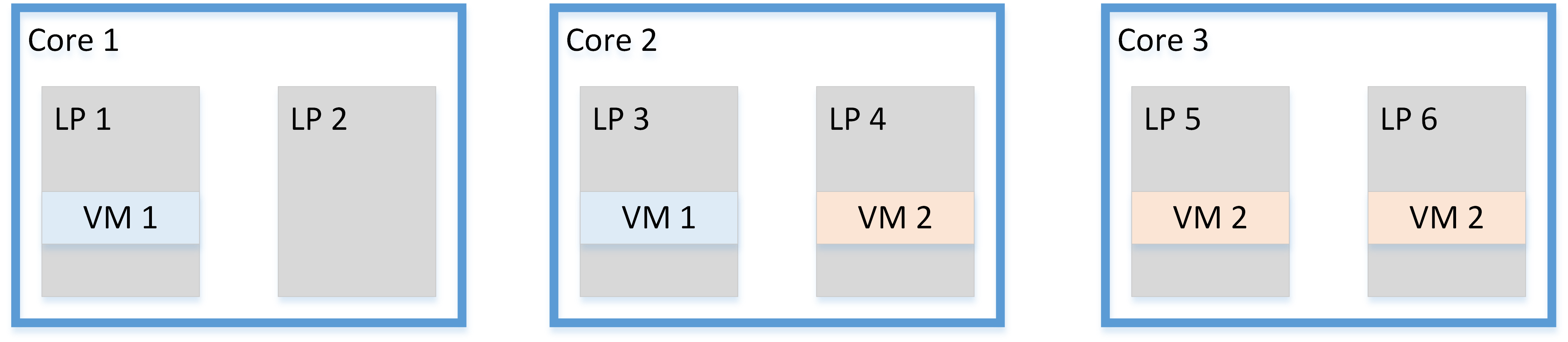
Figure 1. Without Core Scheduling
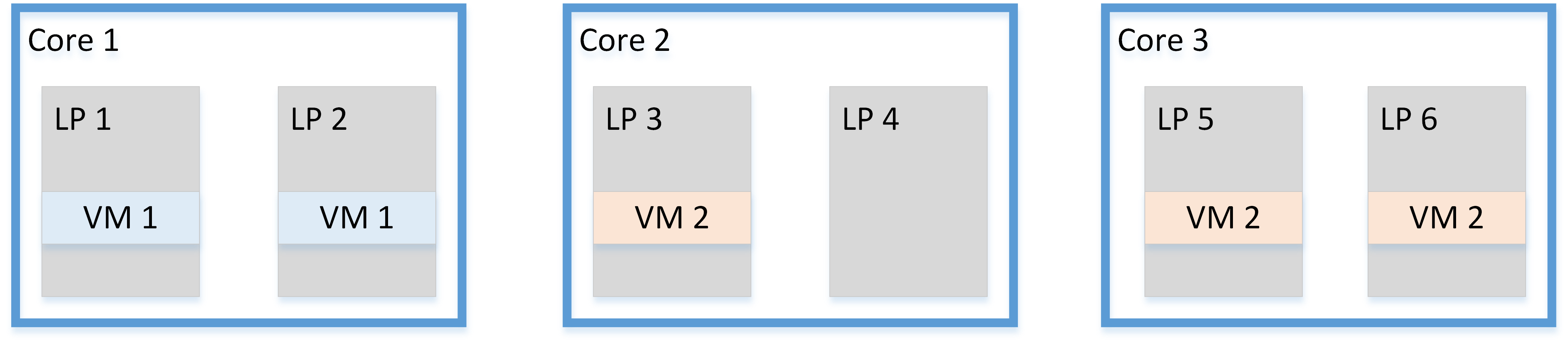
Figure 2. With Core Scheduling
When a VMM hosts untrusted guests it is also possible to enforce these constraints dynamically:
- When the VMM is running on one logical processor and needs to access some secret data (for example, encryption keys), it must deschedule any guest running on the other logical processor of the same physical core, or make sure this never happens with static core assignment.
- There are several options to mitigate when the VMM services an interrupt from a device where the service routine or software interrupt code triggered by the interrupt may load secret data into the L1D:
- Audit each device driver interrupt routine and “white list” those that do not load secret data into the L1D
- Use interrupt affinity to direct the interrupt to be serviced on a logical processor that does not share a core with an untrusted guest.
- The VMM can deschedule the other thread from running guest code until the interrupt completes and flushes the L1D.
- The VMM may schedule threads to run guests at the same time if both logical processors are part of the same guest (or from mutually trusting guests)
Mitigation for hyperthreading is not required when hyperthreading is not supported or not enabled. However, flushing the L1D on each guest entry is still required. Refer to the Appendix: Intel Hyper-Threading Technology section.
VMM Assistance for Guest OS Mitigations
Both the VMM and the guest OS may have mitigations for L1TF, so they should avoid actions that interfere with each others’ mitigations. The VMM should not trust that the guest is performing any particular mitigation, but should follow the conventions below to avoid interfering with any guest mitigations:
- Don't put secret data in the first 4 KB at physical address 0.
- Guests running under a VMM may use the OS mitigations described in the Mitigating OS and SMM section, including the use of all-zero paging structure entries, to protect themselves from malicious applications. These paging structure entries might allow malicious guest applications exploiting L1TF to infer the contents of the 4 KB page at physical address zero.
- As a convention, a VMM can ensure that the page at physical address zero does not contain any secrets. This convention allows guests to use the all-zero value to mitigate vulnerable paging structure entries.
- Deploy EPT mitigations to support guest paging structure mitigations.
- Guests may deploy L1TF mitigations in their paging structure entries, such as those discussed in the Mitigation by Referring to Invalid Memory section. These mitigations may cause guest paging structure entries to refer to invalid guest physical addresses.
- Terminal faults on the EPT tables that provide translation for these addresses need mitigation against L1TF. These EPT entries may be mitigated with the same techniques used for bare-metal OS paging structure entries, such as those described in the Mitigating OS and SMM section.
- Prevent EPT tables from causing L1TF.
- In environments where a guest may be migrated to a different machine, the VMM should provide a consistent value of MAXPHYADDR on all machines in the pool because guests may rely on this value to construct mitigated paging structure entries.
Nested VMM Environments
A guest running in a VMM may itself be another VMM that runs its own guests. Each VMM can choose which CPU capabilities to make available to the guests under its control. The nested VMM should provide an accurate representation of which virtual CPUs are logical processors sharing a physical core on the physical machine so the guest can make efficient and effective mitigation choices.
A nested VMM that finds IA32_FLUSH_CMD is enumerated should check whether IA32_ARCH_CAPABILITIES bit 3 (SKIP_L1DFL_VMENTRY) is set, which indicates that the nested VMM is not required to flush L1D on VMENTER.
First-level VMMs that perform an L1D flush before VMENTER may set SKIP_L1DFL_VMENTRY in the IA32_ARCH_CAPABILITIES value exposed to guests. These VMMs should set SKIP_L1DFL_VMENTRY in any case where a nested VMM may be present.
Summary
Contact your system vendors for firmware updates, and apply all security updates from your software suppliers to protect your systems from L1TF side channel issues.
Affected Processors
Refer to the consolidated list of Affected Processors (2018-2021 tab, L1 Terminal Fault column) for a list of currently supported processors affected by L1TF.
Appendix Intel® Hyper-Threading Technology
The first step in composing an L1TF-based exploit is loading a secret into the L1D. As discussed earlier, secrets can be flushed from the L1D when transitioning between different security contexts. However, processors supporting Intel HT Technology share the L1D and support simultaneously executing code from different security contexts. This means that an L1TF exploit could run on one logical processor on a core while the other (trusted) logical processor on the same physical core simultaneously loads secrets into the L1D, potentially exposing those secrets to the exploit.
Not all Intel HT Technology implementations require mitigation against L1TF exploits. Refer to the List of Processors Affected: L1 Terminal Fault for a complete list of affected processors.
No hyperthreading mitigation is required on affected systems where hyperthreading is unsupported or disabled. However, the general mitigations described in this paper should still be applied as disabling hyperthreading does not in itself provide mitigation for L1TF. Mitigation is also not required in situations where step 2 in the L1TF Limiting Factors section has been entirely mitigated, such as on systems with mitigations in the bare-metal OS that do not run virtual machines.
Determining Hardware Support for Intel HT Technology
It is not universally architecturally possible to reliably determine the underlying hardware support for hyperthreading from an application or a guest OS. Bare-metal VMMs and bare-metal OSes have the ability to modify the behavior of the CPUID instruction, causing its behavior to differ from its bare-metal behavior.
Hyperthreading Enumeration from a Bare-metal OS/VMM
Note The Intel® 64 and IA-32 Architectures Software Developer Manuals Volume 3a, section 8.6 Detecting Hardware Multi-threading Support and Topology, contains the full architectural enumeration of hyperthreading support.
8.9.4 Algorithm for Three-Level Mappings of APIC_ID contains a suggested algorithm that includes detection of hyperthreading. When following that algorithm, if two or more logical processors have the same value for PACKAGE_ID and CORE_ID, mitigations such as those described in the VMM Mitigation for Guest-Based Attacks section may be necessary.
Determining Hardware Support Status
Despite support for hyperthreading in the hardware, software or firmware may choose to not enable the Intel HT Technology feature. Some firmware and OSes provide an option to enable or disable support. As a general rule, systems that report more “logical processors” than “cores” have hyperthreading enabled. However, this might change based on factors such as OS nomenclature or VMMs that do not precisely expose the underlying hardware to the guest OS.
Footnotes
- See Intel® 64 and IA-32 Architectures Software Developer Manuals (Intel SDM), volume 3, chapter 4
- See Intel SDM, volume 3, chapter 4 for the location of reserved bits in the paging structure entries of each paging mode.
- The PML4 does not have a PS bit defined.
- See Intel SDM, Volume 3, Section 36.3
- See Intel SDM, section 8.5
- MSR present if CPUID.(EAX=07H,ECX=0):EDX[28] = 1. Refer to CPUID Enumeration and Architectural MSRs.
- The PS bit is important. Without that detail, zeroed 2 MB / 1 GB entries could be used.
- CPUID.80000008H:EAX[7:0] reports the physical-address width supported by the processor. (for details see Intel SDM volume 3a, chapter 4.1.4 “Enumeration of Paging Features by CPUID”). This width is referred to as MAXPHYADDR
- You can cross-check for affected steppings against the list of updated microcode versions.
Software Security Guidance Home | Advisory Guidance | Technical Documentation | Best Practices | Resources