A General-Purpose Input/Output (GPIO) pin is an uncommitted or shared function physical pin on an integrated circuit or electronic circuit board (such as a microcontroller or memory protection unit (MCU/MPU)), which may be used as an input, output, or both, and is controllable by software.
Intel provides several GPIO pins as part of its products, which Original Equipment Manufacturers (OEMs) and platform manufacturers can connect to other devices on the motherboard. For example, one of the common usages for GPIO is for enabling and disabling devices.
The ability for software to control other devices via GPIO pins is powerful and necessary to provide features, such as those mentioned above, but requires platform manufacturers and BIOS vendors to be cautious in their design and how they configure the pins. Intel provides guidance to both platform manufacturers and firmware/BIOS vendors as to how the pins should be used and how to secure them. If this guidance is not followed, potential platform security vulnerabilities can arise, such as the recently published vulnerability for Trusted Platform Modules (TPMs).
This document provides a summary of Intel's guidance regarding GPIO configuration. Platform manufacturers, BIOS vendors, system software developers, and any ecosystem organization wishing to verify their platforms are properly configured can reference this document for Intel's best practices. Consistent with past Intel guidance, GPIO pins should be locked when necessary, and depending on your organization's threat model, other options for device enablement should be considered.
Background
If certain boot code misconfigures the GPIO configuration lock down, it is possible for a malicious actor to trigger a TPM reset through the platform reset signal (PLTRSTB#).
On some platforms, the PLTRSTB# output signal is connected to the TPM_Reset pin. If the system BIOS does not properly lock the pin configuration as stated by the Intel BIOS Writers Guide, a malicious actor might be able to change the PLTRSTB# pin to a GPIO mode and trigger a partial reset on the platform (without CPU reset) by toggling the pin. Additionally, on some BitLocker* settings, this TPM_Reset signal will eventually allow the attacker to bypass BitLocker protections by undermining TPM behavior design assumptions, and with non-ideal sealing Platform Configuration Registers (PCRs), this may allow a malicious actor to unseal/recover the BitLocker key.
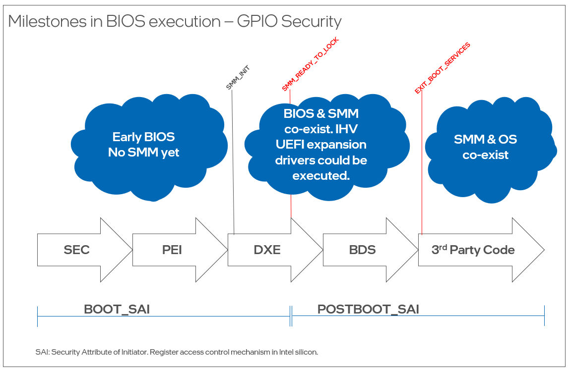
As a best practice, Intel recommends that all GPIO pins whose configuration does not need to change during runtime be locked by BIOS prior to executing any untrusted or third-party code. Developers can reference the GPIO usage guidance for firmware, platform design, and software in the following sections.
Firmware BIOS Guidance
Because GPIO can be used for a variety of purposes and can be easily assigned to devices and functions, it is important to lock down the registers once the platform is configured prior to executing any third-party code, like expansion device firmware and OS loaders. It is important to note that the board design team defines the security posture of the motherboard, whether the board is for client or server products, and which of the GPIO pad configuration registers should be locked by BIOS.
The Platform Control Hub (PCH) allows GPIO configuration registers to be locked down and made Read-Only. As GPIOs are platform specific and provide OEM differentiation capabilities by managing OEM-custom functions over GPIOs, Intel recommends all GPIOs have their configuration locked before any third-party code runs on the platform. Before deviating from Intel guidance, the platform design team for any OEM custom feature must perform a case-by-case analysis of potential risk scenarios. Once locked, the pad can only be unlocked from System Management Mode (SMM). This ensures that only trusted SMM code can change GPIO configuration after the lockdown.
If BIOS and SMM are not inside the trust boundary of the desired OEM custom feature, Intel recommends developers do not use the GPIO and instead find an alternative solution with a better security posture. If BIOS and SMM are inside the trust boundary of the feature, and no third-party code is inside the trust boundary, then Intel recommends locking the GPIO pad containing the GPIO pin used by the feature before the END_OF_DXE event. The best practice is to use a callback function to the SmmReadyToLock event to perform this locking. If the locking needs to be deferred until an independent hardware vendor (IHV) device expansion driver executes, then BIOS shall lock the GPIO pad when the ExitBootServices() callback is called by the OS loader.

GPIO Configuration Register Verification with RWEverything
Each Intel chipset has a register information datasheet which can be downloaded by Intel CNDA customers. Customers can test whether their GPIOs are locked by reading and checking the PADCFGLOCK/PADCFGLOCKTX lock registers by dumping the PADCFGLOCK registers from UEFI or the OS using a tool like RWEverything.
Tables 2, 3, 4 below show examples of GPIO Configuration Lock Bit Listed by CPUID and provide the location of the PLTRSTB# pin configuration lock bit for different CPUIDs, the corresponding address and offsets for the PLTRSTB# pin, and the PADCFGLOCK/PADCFGLOCKTX lock registers. This information can be accessed by using a tool that allows reading physical address over UEFI or the OS (for example, the RWEverything tool).
This PLTRSTB# pin location can also be found in the corresponding chipset PCH External Design Specification. For Raptor Lake P, as an example, it is pin 13, which can be found in Intel® 600 Series Chipset Family and Intel® 700 Series Chipset Family On-Package Platform Controller Hub (PCH) External Design Specification, Volume 1 of 2 and the corresponding address offsets for this PLTRSTB# can be found based on pin 13 in Intel® 600 Series and Intel® 700 Series Chipset Family On-Package Platform Controller Hub (PCH) External Design Specification - Volume 2 of 2. From PCH volume 2, Pad Config Lock (PADCFGLOCK_GPPC_B_13) can be found under GPIO community 0 section. From PCH volume 1, port ID 6EH (0x 6E) can be found under table 99 Private Configuration Target Port ID community 0.
Steps to Run the Test
- Identify the Pad Configuration Lock registers (PADCFGLOCK and PADCFGLOCKTX) that contain the lock bits for the PLTRSTB# pin on the targeted system. Note their address offsets, as well as the bit field number for the lock bit field. For convenience, you may look them up on the table below. Note the Sideband Port ID as well. For instance, for Arrow Lake S (CPUID C0662), the offsets are 0x120 and 0x124, respectively; the bit field number is 13 for both, and the Port ID is 6Dh.
- Get the value of the Sideband Register Access Base Address for the targeted system. This 64-bit base address can be read from the PCI Configuration registers at offsets 10h (lower 32 bits) and 14h (upper 32 bits) of the P2SB Bridge in the PCH. For example, for Arrow Lake S (CPUID C0662), we obtained a base address of 5F_F000_0000h.
- Compute the system (physical) address of the PADCFGLOCK and PADCFGLOCKTX registers using this formula: System Address=Sideband Register Access Base Address+Sideband Port ID≪16+Register Offset. For Arrow Lake S (CPUID C0662), the resulting system addresses for the PADCFGLOCK and PADCFGLOCKTX registers are 5F_F06D_0120h and 5F_F06D_0124h, respectively.
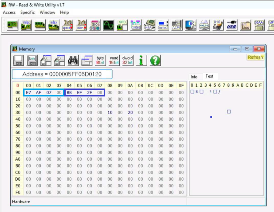
- Use the RWEverything memory dump module to read the GPIO memory-mapped registers starting at the calculated system address. For our Arrow Lake S (CPUID C0662) example, we input physical address 5F_F06D_0120h, as seen in Figure 2: Read/Write Utility Output.

Figure 2: Read/Write Utility Output - Write down the values of the PADCFGLOCK and PADCFGLOCKTX registers. They each span four bytes, and the bytes are displayed in reverse order by default. In the example, PADFCGLOCK=0007_AFE7h and PADCFGLOCKTX=002F_EFBBh.
- Check if the bit fields corresponding to the PLTRSTB# locks are set. In our example, the bit field number for both locks is 13. Converting the register values to binary, we have the values shown in Table 1:
Table 1: Alder Lake S PADCFGLOCK and PADCFGLOCKTX Register Values
| Register | Value (hexadecimal) | Value (binary) |
|---|---|---|
| PADCFGLOCK | 00 07 AF E7 | 0000 0000 0000 0111 1010 1111 1110 0111 |
| PADCFGLOCKTX | 00 2F EF BB | 0000 0000 0010 1111 1110 1111 1011 1011 |
Bit 13 (counting from right to left, starting at 0) is highlighted, and we can see it is set in both cases, indicating that both the PADCFGLOCK and the PADCFGLOCKTX are set for the PLTRSTB# pin.
This method of directly reading and verifying that the lock bit is set confirms whether BIOS did or did not lock the PLTRSTB# pin configuration. If configuration is not locked, this issue may or may not be exploitable depending on specific platform design choices. For example, in the recently published vulnerability for Trusted Platform Modules, PLTRSTB# triggers a partial reset on some of the platforms. If the platform executes a full system reset by triggering PLTRSTB#, then the issue may not be exploitable because the CPU gets reset, and therefore the exploit cannot continue unsealing the BitLocker key.
Table 2: Example of GPIO Configuration Lock Bit Listed by CPUID (Mobile)
| CPUID | Code Name/Microarchitecture | Pin | Sideband Port ID | PadCfgLock Register Offset | PadCfgLock Bit Field | PadCfgLockTX Register Offset | PadCfgLockTx Bit Field |
|---|---|---|---|---|---|---|---|
|
A06A4
|
Meteor Lake Mobile
|
GPP_B_13 |
0xD5 |
0x110 |
13 |
0x114 |
13 |
|
B0671 B06F2 B06F5 B06A2 B06A3 |
Raptor Lake HX Raptor Lake P Raptor Lake H Raptor Lake U |
GPP_B_13 |
0x6D |
0x110 |
13 |
0x114 |
13 |
|
906A3 906A4 B06E0
|
Alder Lake-N Alder Lake U Arizona Beach Alder Lake H Alder Lake P |
GPP_B_13 |
0x6E |
0x80 |
13 |
0x84 |
13 |
|
806EB 806C1 806C2 806D1 A0671 |
Tiger Lake P Tiger Lake U Tiger Lake H35 Tiger Lake U Refresh Tiger Lake H Rocket Lake Whiskey Lake U |
GPP_B_13 |
0x6E |
0x80 |
13 |
0x84 |
13 |
|
A0660 A0661 |
Comet Lake U (always packaged with 400 Series PCH) |
GPP_B_13 |
0x6E |
0x88 |
13 |
0x8C |
13 |
While mobile processors can be identified with CPUID and the GPIO lock bit, this may not the case with desktop processors because the CPU and PCH combinations are flexible to enable backward and forward compatibility.
For desktop processors, the GPIO pin should be identified by the chipset series instead of processor’s CPUID, as shown in Table 3.
Table 3: Example of GPIO Configuration Lock Bit Listed by PCH (Desktop)
| Project PCH Series | CPUID | Pin | SB Port ID | Padcfglock Address Offset | Padcfglock Bit Field | PadcfglockTX Address Offset | padcfglockTx Bit Field | Reference for pin name, bit field, and PortID (found in community) | Reference for Offsets |
|---|---|---|---|---|---|---|---|---|---|
|
Alder Lake S (always pairs with Intel 600 or 700 series PCH) Raptor Lake S (always pairs with Intel 600 or 700 series PCH) |
90672 90675
|
GPP_B_13 |
0x6D |
0x110 |
13 |
0x114 |
13 |
Intel® 700 Series Chipset Family Platform Controller Hub Datasheet, Volume 1 of 2 |
Intel® 700 Series Chipset Family Platform Controller Hub Datasheet - Volume 2 of 2 |
|
Comet Lake Desktop (paired with 400 Series PCH) |
A0655 |
GPP_B_13 |
0x6E |
0x88 |
13 |
0x8C |
13 |
Intel® 400 Series Chipset Family Platform Controller Hub (PCH) Datasheet, Volume 1 of 2 |
Intel® 400 Series Chipset Family Platform Controller Hub Datasheet Volume 2 of 2 |
|
Comet Lake Desktop (paired with 495 Series PCH) |
A0655 |
GPP_B_13 |
0x6E |
0x88 |
13 |
0x8C |
13 |
Intel® 495 Series Chipset Family On-Package PCH Datasheet, Volume 1 of 2 |
Intel® 495 Series Chipset Family On-Package PCH Datasheet Volume 2 of 2 |
|
Comet Lake Desktop (paired with B460 / H410 PCH) |
A0655 |
GPP_B_13 |
0xAF |
0xA8 |
13 |
0xAC |
13 |
Intel® B460 and H410 Chipset Platform Controller Hub Datasheet Volume 1 of 2 |
Intel® B460 and H410 Chipset Platform Controller Hub Datasheet Volume 2 of 2 |
|
Granite Rapids Workstation (always pairs with Intel Series 800 PCH) |
A06D0 A06D1 |
GPP_B_13 |
0x6D |
0x120 |
13 |
0x124 |
13 |
Introduction - 1.5 - ID:728144 | Intel® 800 Series Chipset Family Platform Controller Hub (PCH) |
|
|
Arrow Lake S (always pairs with Intel Series 800 PCH) |
C0662 |
GPP_B_13 |
0x6D |
0x120 |
13 |
0x124 |
13 |
Introduction - 1.5 - ID:728144 | Intel® 800 Series Chipset Family Platform Controller Hub (PCH) |
Table 4: Example of GPIO Configuration Lock Bit Listed by CPUID (Server)
| CPUID | Code Name/Microarchitecture | Pin | Sideband Port ID | PadCfgLock Register Offset | PadCfgLock Bit Field | PadCfgLockTX Register Offset | PadCfgLockTx Bit Field |
|---|---|---|---|---|---|---|---|
|
306F2 406F1 |
Haswell Broadwell |
See explanation below in Example Register Information section | |||||
|
506F1 |
Denverton |
GPP_B_13 |
0xC5 |
0xA8 |
8 |
0xAC |
8 |
|
806F7 806F8 C06F2 |
Sapphire Rapids Emerald Rapids |
GPP_D_11 |
0x6D |
0x108 |
11 |
0x10C |
11 |
|
50653 50654 50656 606A6
|
Skylake Server Skylake D, Bakerville Skylake X Cascade Lake Server Cascade Lake X Ice Lake Xeon SP |
GPP_B_13 |
0xAF |
0x68 |
13 |
0x6C |
13 |
Example Register Information
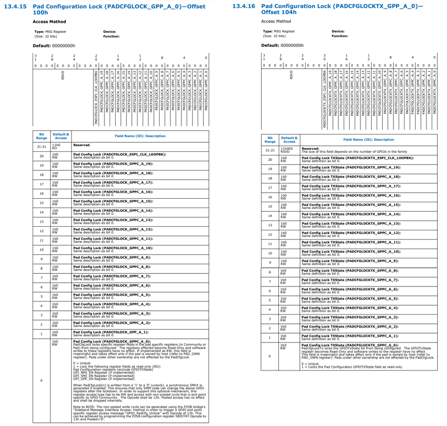
The below GPIO PAD Configuration Lock register information is an excerpt from the Intel® C740 Series Chipset Platform Controller Hub External Design Specification (Emmitsburg) for Intel platforms code named Sapphire Rapids and Emerald Rapids. The description for BIT0 of PADCFGLOCK_GPP_A_0 and PADCFGLOCKTX_GPP_A_0 applies to all bits.

The GPIO architecture used in Intel platforms has changed starting from platforms code named Lewisburg. For processors code named Haswell and Broadwell, the method for GPIO registers lockdown can be found in section 16.4 of Intel 8 Series C220 Series Chipset Family, Mobile 4th Generation Intel® Core™ Processor Family IO, and Wellsburg Platform Controller Hub BIOS Specification (Haswell/Grovepoint). PCH provides a single GPIO register lock-down bit, which locks all the GPIO registers. All GPIO configuration registers become Read-Only when the GPIO Lockdown Enable (GLE) bit, D31:F0:Reg 4Ch[0], is set. To unlock the GPIO registers, the GLE bit must be cleared. When the GLE bit is changed from 1 to 0, a system management interrupt (SMI) is generated. The SMI handler can do the due diligence to protect the GPIO configuration registers.
GPIO Configuration Register Verification with CHIPSEC
Intel also provides the CHIPSEC tool to check the configuration settings of the platform. CHIPSEC is a framework for analyzing platform-level security of hardware, devices, system firmware (BIOS/UEFI) and platform components, low-level protection mechanisms, and the configuration of various platform components. CHIPSEC includes a security test suite, tools for accessing various low-level interfaces, and forensic capabilities, and can be run on Windows*, Linux*, and UEFI shell.
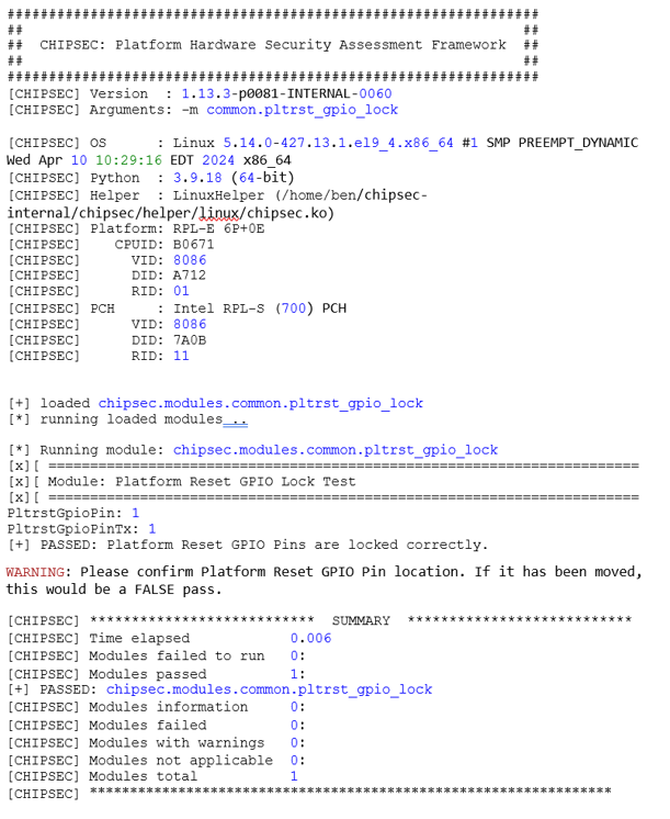
The test module common.pltrst_gpio_lock in the CHIPSEC tool audits the OEM configuration setting for the platform reset pins and the configuration’s susceptibility to a potential partial reset. Instructions for installing and general information for using CHIPSEC can be found in the CHIPSEC Installation Overview. Access for Intel CNDA customers can be found in the CHIPSEC Download Instructions.
To Run the Test
Assuming CHIPSEC is already installed on the target system, run the following command:
python chipsec_main.py -m common.pltrst_gpio_lock
Example Log File
The following log file was generated when running the common.pltrst_gpio_lock test on a system that had both locks set for the PLTRSTB# pin.

Platform Design Guidance
GPIO pins should be assigned with a clear purpose. Each GPIO pin should be assigned one specific function.
- Designs should analyze using a single GPIO for input and output at runtime. Depending on the platform-specific design, a GPIO pin may be used and not locked. The threat model should be consistent with the usage to prevent electrical contention that may lead to aging or physical damage or to prevent permanent denial of service (PDoS). In some cases, SMM protection may be enough to handle the configuration. In other cases, where BIOS or SMM is not in the Trusted Computing Base (TCB) for the given feature, a different method should be used.
- Security-sensitive GPIO (such as TPM connection) should not be shared with other functionality.
- The platform should not allow PLTRSTB# to reset devices without resetting the whole system for a commercial design.
Software Guidance
If firmware/BIOS/OS needs to leave a GPIO pin unlocked to allow configuration by software, a platform-level security analysis must be done. In such case, the analysis must consider that the OS is in the Trusted Computing Base (TCB) for the platform-specific feature. Any potential electrical contention or any other platform specific usages that are not meant for OS to handle, or that OS should be excluded from TCB, should be locked by BIOS. For example, the TPM_Reset issue is one of these features (TPM_RESET). While there is no electrical contention, TPM_RESET leads to a potential security issue by allowing the OS to reset the TPM, undermining BIOS protections.
Additional guidance for the TPM GPIO fail case:
- Software should use the appropriate PCRs that contain system-generated measurements. For defense in depth, Intel recommends that applications use hardware root-of-trust programmed PCRs instead of flag-like PCRs.
- TPM reset attacks can be mitigated by software using PCR0, which is programmed by Intel’s hardware root of trust, Intel® BootGuard. The Intel BootGuard Authentication Code Module (ACM) establishes a strong hardware root of trust by measuring the initial BIOS into TPM PCR0 using TPM locality 3. TPM locality 3 is limited to ACMs only, so this measurement is not spoofable by a malicious actor even after resetting the PCRs. The TPM GPIO Fail attack would also be detectable through software attestation based on PCR0.
- TPM reset attacks can also be mitigated using Intel® Trusted Execution Technology (Intel® TXT). Intel TXT provides a hardware-based, dynamic root of trust that is not spoofable by software. Information about Intel TXT can be found in the Intel® Trusted Execution Technology (Intel® TXT): Software Development Guide.
References
Trusted Computing Group CPU to TPM Bus Protection Guidance for Active Attacks
TCG PC Client Platform TPM Profile Specification for TPM 2.0. See section 9.2 HW implementation of TPM
TPM GPIO fail: How bad OEM firmware ruins TPM security
TPM GPIO Fail Ycombinator Discussion
Alder Lake N and Twin Lake Platform Design Guide
Raptor Lake S/S Refresh LGA Platform Design Guide
Intel® 500 Series Chipset Family On-Package Platform Controller Hub (Tiger Lake)
Grand Ridge BIOS Writers Guide (Emmitsburg/Granite Rapids/Sierra Forest)
Intel® Core™ Processors Technical Resources
Intel® 495 Series Chipset Family On-Package PCH Datasheet Volume 2 of 2
Users with signed NDAs can access additional resources including platform-specific design guides and specifications. Titles to search for include:
Alder Lake, Raptor Lake, Twin Lake PCH BIOS Writers Guide.
Coffee Lake Platform Controller Hub External Design Specification
Coffee Lake Platform Design Guide
Eagle Stream Platform Design Guide (Sapphire Rapids/Emerald Rapids)
Eagle Stream Platform BIOS Writer's Guide (Sapphire Rapids/Emerald Rapids)
Intel® C740 Series Chipset Platform Controller Hub External Design Specification (Sapphire Rapids/Emerald Rapids
Emmitsburg Platform Controller Hub (PCH) BIOS Specification (Sapphire Rapids/Emerald Rapids)
Intel® C610 Series Chipset and Intel® X99 Chipset Platform Controller Hub (PCH) – External Design Specification (EDS) (Haswell/Broadwell)
Intel 8 Series C220 Series Chipset Family, Mobile 4th Generation Intel® Core™ Processor Family IO, and Wellsburg Platform Controller Hub BIOS Specification (Haswell/Grovepoint)
Idaville LCC Platform Design Guide (Ice Lake)
Intel® Xeon® Processor Scalable Family (Skylake and Cascade Lake) BIOS Writer's Guide
Tiger Lake UP3 UP4 H35 UP3 Refresh Platform Design Guide
Tiger Lake H Platform Design Guide
Comet Lake U PCH (400 Series Chipset) Intel 400 Series Chipset Family On-Package Platform Controller Hub (PCH) External Design Specification (EDS) Volume 1 of 2