This article describes the concept of jumbo frames and how support for that feature is implemented in Open vSwitch* (OvS) with the Data Plane Development Kit (DPDK). It outlines how to configure jumbo frame support for DPDK-enabled ports on an OvS bridge and also provides insight into how OvS DPDK memory management for jumbo frames works. Finally, it details two tests that demonstrate jumbo frames in action on an OvS DPDK deployment and looks at another that demonstrates performance gains achieved through the use of jumbo frames. This guide was written with general OvS users in mind, who want to know more about the jumbo frame feature and apply it in their OvS DPDK deployment.
At the time of this writing, jumbo frame support for OvS DPDK is available on the OvS master branch, and also the 2.6 branch. Installation steps for OvS with DPDK can be found here.
Jumbo Frames
A jumbo frame is distinguished from a “standard” frame by its size: any frame larger than the standard Ethernet MTU (Maximum Transmission Unit) of 1500B is characterized as a jumbo frame. The MTU is the largest amount of data that a network interface can send in a single unit. If the network interface wants to transmit a large block of data, it needs to fragment the data into multiple units of size MTU, each unit containing part of the data, plus the required network layer encapsulation headers. If instead, the network devices take advantage of jumbo frames, a significantly larger amount of application data can be carried in a single frame, eliminating much of the overhead incurred by duplication of encapsulation headers.
Thus, the primary benefit of using jumbo frames is the improved data-to-overhead ratio that they provide—the same amount of data can be communicated with significantly less overhead. As a corollary, the resultant reduced packet count also means that the kernel needs to handle fewer interrupts, which reduces the CPU load (N/A in DPDK).
Usage of Jumbo Frames
Jumbo frames are typically beneficial in environments in which large amounts of data need to be transferred, such as Storage Area Networks (SANs), where they improve transfer rates for large files. Many SANs use the Fibre Channel over Ethernet (FCoE) protocol to consolidate their storage and network traffic on a single network; FCoE frames have a minimum payload size of 2112B, so jumbo frames are crucial if fragmentation is to be avoided. Jumbo frames are also useful in overlay networks, where the amount of data that a frame can carry is reduced below the standard Ethernet MTU, as a result of the addition of tunneling headers; boosting the MTU can negate the effects of the additional encapsulation overhead.
Jumbo Frames in OVS
Network devices (netdevs) generally don’t support jumbo frames by default but can be easily configured to do so. Jurisdiction over the MTU of traditional logical network devices is typically beyond the remit of OvS and is instead governed by the kernel’s network stack. A netdev’s MTU can be queried and modified using standard network management tools, such as ifconfig in Linux*. Figure 1 illustrates how ifconfig may be used to increase the MTU of network device p3p3 from 1500 to 9000. The MTU of kernel-governed netdevs is subsequently honored by OVS when those devices are added to an OvS bridge.
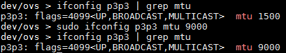
Figure 1: Configuring the MTU of a network device using ifconfig.
OvS DPDK devices cannot avail of ifconfig, however, as control of DPDK-enabled netdevs is maintained by DPDK poll mode drivers (PMDs) and not standard kernel drivers. The OvS DPDK jumbo frames feature provides a mechanism which OvS employs to modify the MTU of OvS DPDK netdevs, thus increasing their maximum supported frame size.
Jumbo Frames in OvS DPDK
This section provides an overview of how frames are represented in both OvS and DPDK, and how DPDK manages packet buffer memory. It then describes how support for jumbo frames is actually implemented in OvS DPDK.
In OvS, frames are represented in the OvS datapath (dpif) layer as dp_packets (datapath packets), as illustrated in Figure 2. A dp_packet contains a reference to the packet buffer itself, as well as some additional metadata and offsets that OvS uses to process the frame as it traverses the vSwitch.
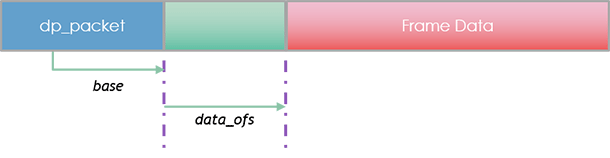
Figure 2: Simplified view of Open vSwitch* datapath packet buffer.
In DPDK, a frame is represented by the message buffer data structure (rte_mbuf, or just mbuf for short), as illustrated in Figure 3. An mbuf contains metadata which DPDK uses to process the frame, and a pointer to the message buffer itself, which is stored in contiguous memory just after the mbuf. The mbuf’s buf_addr attribute points to the start of the message buffer, but the frame data itself actually begins at an offset of data_off from buf_addr. The additional data_off bytes, which is typically RTE_PKTMBUF_HEADROOM (128 bytes) long, are allocated in case additional headers need to be prepended before the packet during processing.

Figure 3: Data Plane Development Kit message buffer (‘mbuf’).
Unsurprisingly then, in OvS DPDK, a frame is represented by a dp_packet, which contains an rte_mbuf. The resultant packet buffer memory layout is shown in Figure 4.

Figure 4: Open vSwitch Data Plane Development Kit packet buffer.
DPDK is targeted for optimized packet processing applications; for such applications, allocation of packet buffer memory from the heap at runtime is much too slow. Instead, DPDK allocates application memory upfront during initialization. To do this, it creates one or more memory pools (mempools) that DPDK processes can subsequently use to create mbufs at runtime with minimum overhead. Mempools are created with the DPDK rte_mempool_create function.
struct rte_mempool *
rte_mempool_create(const char *name, unsigned n, unsigned elt_size,
unsigned cache_size, unsigned private_data_size,
rte_mempool_ctor_t *mp_init, void *mp_init_arg,
rte_mempool_obj_cb_t *obj_init, void *obj_init_arg,
int socket_id, unsigned flags)
The function returns a reference to a mempool containing a fixed number of elements; all elements within the mempool are the same size. The number of elements and their size are determined by the respective values of the cache_size and elt_size parameters provided to rte_mempool_create.
In the case of OvS DPDK, elt_size needs to be big enough to store all of the data that we observed in Figure 4: Open vSwitch Data Plane Development Kit packet buffer; this includes the dp_packet (and the mbuf that it contains), the L2 header and CRC, the IP payload, and the mbuf headroom (and tailroom, if this is required). By default, the value of elt_size is only large enough to accommodate standard-sized frames (i.e., 1518B or less); however, if it were possible to specify a much larger value, it would allow OvS DPDK to support jumbo frames in a single mbuf segment.
In OvS, a subset of a net device’s properties can be modified on the command line using the ovs-vsctl utility; OvS 2.6 introduces a new Interface attribute, mtu_request, which users can leverage to adjust the MTU of DPDK devices. For example, to add a physical DPDK port (termed dpdk port in OvS DPDK) with a Layer 3 MTU of 9000B to OvS bridge br0:
ovs-vsctl add-port br0 dpdk0 -- set Interface dpdk0 type=dpdk -- set Interface dpdk0 mtu_request=9000
Alternatively, to reduce the MTU of the same port to 6000 after it has been added to the bridge:
ovs-vsctl -- set Interface dpdk0 mtu_request=6000
Note that mtu_request refers to the Layer 3 MTU; OvS DPDK allows an additional 18B for Layer 2 header and CRC, so the maximum permitted frame size in the above examples is 9018B and 6018B, respectively. Additionally, ports that use the same MTU share the same mempool; if a port has a different MTU than existing ports, OvS creates an additional mempool for it (assuming that there is sufficient memory to do so). Mempools for MTUs that are no longer used are freed.
Functional Test Configuration
This section outlines two functional tests that demonstrate jumbo frame support across OvS DPDK physical and guest (dpdkvhostuser) ports. The first test simply demonstrates support for jumbo frames across disparate DPDK port types, while the second additionally shows the effects of dynamically altering a port’s MTU at runtime. Both tests utilize a “hairpin” traffic path, as illustrated in Figure 5. During testing, validation of jumbo frame traffic integrity occurs in two places: (1) in the guest’s network stack via tcpdump, and (2) on the traffic generator’s RX interface, via packet capture and inspection.

Test Environment
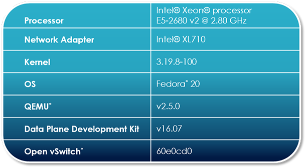
The DUT used during jumbo frame testing is configured as per Table 1. Where applicable, the software component used is listed with its corresponding commit ID or tag.
Traffic Configuration
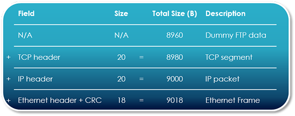
Dummy TCP traffic for both tests is produced by a physical generator; salient traffic attributes are outlined below in Table 2.

9018B frames are used during testing. Note the IP packet size of 9000B and the data size of 8960B, as described in Figure 6; they’ll be important later on during testing.
NIC Configuration
No specific configuration of the NIC is necessary in order to support jumbo frames, as the DPDK PMD configures the NIC to support oversized frames as per the user-supplied MTU (mtu_request). The only limitation is that the user-supplied MTU must not exceed the maximum frame size that the hardware itself supports. Consult your NIC datasheet for details. At the time of writing, the maximum frame size supported by the Intel® Ethernet Controller XL710 network adapter is 9728B1, which yields a maximum mtu_request value of 9710.
vSwitch Configuration
Compile DPDK and OvS, mount hugepages, and start up the switch as normal, ensuring that the dpdk-init, dpdk-lcore-mask, and dpdk-socket-mem parameters are set. Note that in order to accommodate jumbo frames at the upper end of the size spectrum, ovs-vswitchd may need additional memory; in this test, 4 GB of hugepages are used.
ovs-vsctl –no-wait set Open_vSwitch.other_config:dpdk-socket-mem=4096,0
Create an OvS bridge of datapath_type netdev, and add 2 x DPDK phy ports, and 2 x guest ports. When adding the ports, specify the mtu_request parameter as 9000. This will allow frames up to a maximum of 9018B to be supported. Incidentally, the value of mtu_request may be modified dynamically at runtime, as we’ll observe later in Test Case #2
ovs-vsctl add-br br0 –- set Bridge br0 datapath_type=netdev

	ovs-vsctl –no-wait set Open_vSwitch.other_config:pmd-cpu-mask=6

	ovs-vsctl add-port br0 dpdk0 -- set Interface dpdk0 type=dpdk -- set Interface dpdk0 mtu_request=9000

	ovs-vsctl add-port br0 dpdk1 -- set Interface dpdk0 type=dpdk -- set Interface dpdk1 mtu_request=9000

	ovs-vsctl add-port br0 dpdkvhostuser0 -- set Interface dpdkvhostuser0 type=dpdkvhostuser -- set Interface dpdkvhostuser0 mtu_request=9000

	ovs-vsctl add-port br0 dpdkvhostuser1 -- set Interface dpdkvhostuser1 type=dpdkvhostuser -- set Interface dpdkvhostuser1 mtu_request=9000
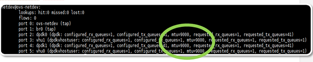
Inspect the bridge to ensure that MTU has been set appropriately for all ports. Note that all of the ports listed in Figure 7 display an MTU of 9000.
ovs-appctl dpctl/show
Alternatively, inspect the MTU of each port in turn.
ovs-vsctl get Interface [dpdk0|dpdk1|dpdkvhostuser0|dpdkvhostuser1] mtu
Sample output for this command is displayed in Figure 8.

Start the Guest
sudo -E $QEMU_DIR/x86_64-softmmu/qemu-system-x86_64 -name us-vhost-vm1 -cpu host -enable-kvm \
-m $MEM -object memory-backend-file,id=mem,size=$MEM,mem-path=$HUGE_DIR,share=on -numa node,memdev=mem -mem-prealloc -smp 2 -drive file=/$VM1 \
-chardev socket,id=char0,path=$SOCK_DIR/dpdkvhostuser0 \
-netdev type=vhost-user,id=mynet1,chardev=char0,vhostforce -device virtio-net-pci,mac=00:00:00:00:00:01,netdev=mynet1,mrg_rxbuf=on \
-chardev socket,id=char1,path=$SOCK_DIR/dpdkvhostuser1 \
-netdev type=vhost-user,id=mynet2,chardev=char1,vhostforce -device virtio-net-pci,mac=00:00:00:00:00:02,netdev=mynet2,mrg_rxbuf=on \
--nographic -vnc :1 \
Guest Configuration
Jumbo frames requires end-to-end configuration, so we’ll need to set the MTU of the relevant guest network devices to 9000, to avoid fragmentation of jumbo frames in the VM’s network stack.
ifconfig eth1 mtu 9000

	ifconfig eth2 mtu 9000
Configure IP addresses for the network devices, and then bring them up.
ifconfig eth1 5.5.5.2/24 up

	ifconfig eth2 7.7.7.2/24 up
Enable IP forwarding; traffic destined for the 7.7.7.0/24 network will be returned to the vSwitch via the guest’s network stack.
sysctl net.ipv4.ip_forward=1
Depending on the traffic generator setup, a static ARP entry for the traffic destination IP address may be required:
arp -s 7.7.7.3 00:00:de:ad:be:ef
Test Case #1
This test simply demonstrates the jumbo frame feature on OvS DPDK for dpdk and dpdkvhostuser port types.
Initial setup is as previously described. Simply start continuous traffic to begin the test.
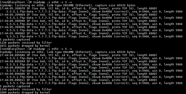
In the guest, turn on tcpdump for the relevant network devices while traffic is live. The output from the tool confirms the presence of jumbo frames in the guest’s network stack. In the sample command lines below, tcpdump output is limited to 20 frames on each port to prevent excessive log output.
tcpdump -i eth1 –v –c 20 # view ingress traffic

	tcpdump -i eth2 –v –c 20 # view egress traffic
The output of tcpdump is demonstrated in Figure 9: tcpdump of guest network interfaces. It shows that the length of the IP packets received and subsequently transmitted by the guest is 9000B (circled in blue) and the length of the corresponding data in the TCP segment is 8960B (circled in green). Note that these figures match the traffic profile described in Figure 6: Jumbo frame test traffic breakdown.
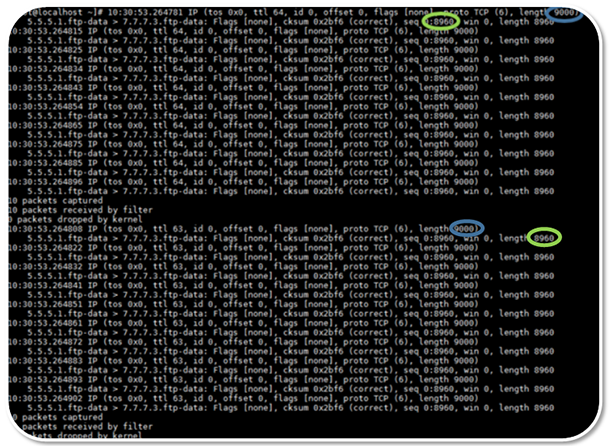
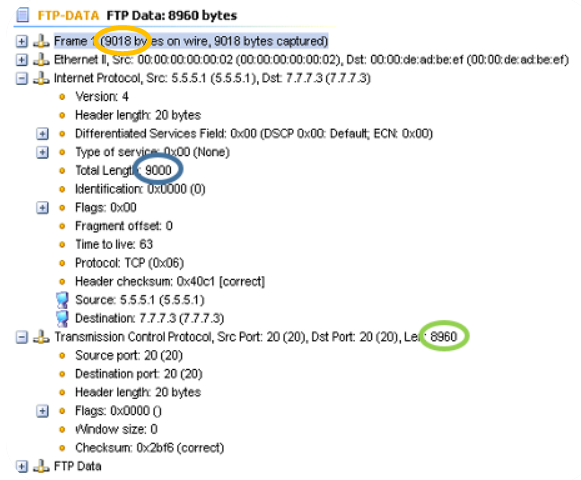
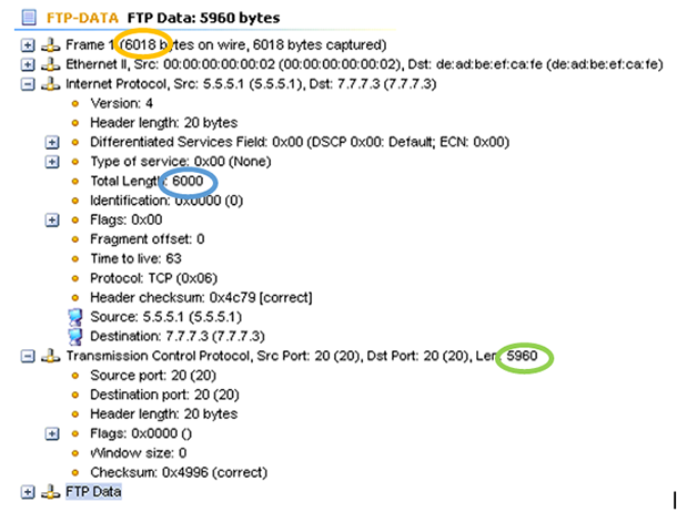
Figure 10 shows the contents of a packet captured at the test endpoint, the traffic generator’s RX port. Note that the Ethernet frame length is 9018B as expected (circled in orange). Additionally, the IP packet length and data length remain 9000B and 8960B, respectively. Since these values remain unchanged for frames that traverse the vSwitch and through a guest, we can conclude that the 9018B frames sent by the generator were not fragmented, thus demonstrating support for jumbo frames for OVS DPDK dpdk and vhostuser ports.
Test Case #2
This test demonstrates runtime modification of a DPDK-based netdev’s MTU, using the ovs-vsctl mtu_request parameter.
Setup is identical to the previous test case; to kick off the test, just start traffic (9018B frames, as per Table 2: Jumbo frame test traffic configuration) on the generator’s Tx interface.
Observe that 9k frames are supported throughout the entire traffic path, as per Test Case #1.
Now reduce the MTU of one of the dpdk (that is, Phy) ports to 6000. This configures the NIC’s Rx port to accept frames with a maximum size of 6018B.2
ovs-vsctl set Interface dpdk0 mtu_request=6000
Verify that MTU was set correctly for dpdk0 and that the MTU for the remaining ports remain unchanged, as per Figure 11.
ovs-vsctl dpctl/show
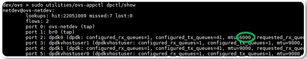
Observe that traffic is no longer received by the vSwitch, as it was dropped by the NIC due to its size, as per Figure 12. The lack of flows installed in the datapath indicates that it is not currently handling any flows.
ovs-appctl dpctl/dump-flows
Running tcpdump in the guest provides additional confirmation that packets are not reaching the guest.
Next reduce the traffic frame size to 6018B in the generator; this frame size is permitted by the NIC’s configuration, as per the previously supplied value of mtu_request. Observe that these frames now pass through to the guest; as expected, the IP packet size is 6000B, and the TCP segment contains 5960B of data (Figure 13).
Examining traffic captured at the test endpoint, it is confirmed that 6018B frames were received, with IP packet and data lengths as expected.
Performance Test Configuration
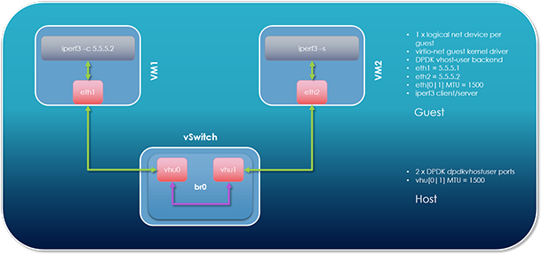
This section demonstrates the performance benefits of jumbo frames in OVS DPDK. In the described sample test, two VMs are spawned on the same host, and traffic is transmitted between them. One VM runs an iperf3 server, while the other runs an iperf3 client. iperf3 initiates a TCP connection between the client and server, and transfers large blocks of TCP data between them. Test setup is illustrated in Figure 15.
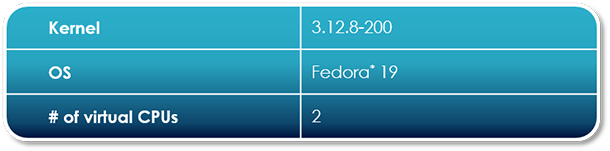
Test Environment
The host environment is as described previously, in the “Functional Test Configuration” section.
The guest environment is as described below, in Figure 16.
vSwitch Configuration
Start OVS, ensuring that the relevant OVSDB DPDK fields are set appropriately.
sudo -E $OVS_DIR/utilities/ovs-vsctl --no-wait set Open_vSwitch . other_config:dpdk-init=true
sudo -E $OVS_DIR/utilities/ovs-vsctl --no-wait set Open_vSwitch . other_config:dpdk-lcore-mask=0x10
sudo -E $OVS_DIR/utilities/ovs-vsctl --no-wait set Open_vSwitch . other_config:dpdk-socket-mem=4096,0
sudo -E $OVS_DIR/vswitchd/ovs-vswitchd unix:$DB_SOCK --pidfile --detach --log-file &
Create an OVS bridge, and add two dpdkvhostuser ports.
sudo -E $OVS_DIR/utilities/ovs-vsctl --timeout 10 --may-exist add-br br0 -- set Bridge br0 datapath_type=netdev -- br-set-external-id br0 bridge-id br0 -- set bridge br0 fail-mode=standalone
sudo -E $OVS_DIR/utilities/ovs-vsctl --timeout 10 set Open_vSwitch . other_config:pmd-cpu-mask=6
sudo -E $OVS_DIR/utilities/ovs-vsctl --timeout 10 add-port br0 $PORT0_NAME -- set Interface $PORT0_NAME type=dpdkvhostuser
sudo -E $OVS_DIR/utilities/ovs-vsctl --timeout 10 add-port br0 $PORT1_NAME -- set Interface $PORT1_NAME type=dpdkvhostuser
Start the guests, ensuring that mergeable buffers are enabled.
sudo -E taskset 0x60 $QEMU_DIR/x86_64-softmmu/qemu-system-x86_64 -name us-vhost-vm1 -cpu host -enable-kvm -m 4096M -object memory-backend-file,id=mem,size=4096M,mem-path=$HUGE_DIR,share=on -numa node,memdev=mem -mem-prealloc -smp 2 -drive file=$VM1 -chardev socket,id=char0,path=$SOCK_DIR/dpdkvhostuser0 -netdev type=vhost-user,id=mynet1,chardev=char0,vhostforce -device virtio-net-pci,mac=00:00:00:00:00:01,netdev=mynet1,mrg_rxbuf=on,csum=off,gso=off,guest_csum=off,guest_tso4=off,guest_tso6=off,guest_ecn=off --nographic -vnc :1
sudo -E taskset 0x180 $QEMU_DIR/x86_64-softmmu/qemu-system-x86_64 -name us-vhost-vm2 -cpu host -enable-kvm -m 4096M -object memory-backend-file,id=mem,size=4096M,mem-path=$HUGE_DIR,share=on -numa node,memdev=mem -mem-prealloc -smp 2 -drive file=$VM2 -chardev socket,id=char1,path=$SOCK_DIR/dpdkvhostuser1 -netdev type=vhost-user,id=mynet2,chardev=char1,vhostforce -device virtio-net-pci,mac=00:00:00:00:00:02,netdev=mynet2,mrg_rxbuf=on,csum=off,gso=off,guest_csum=off,guest_tso4=off,guest_tso6=off,guest_ecn=off --nographic -vnc :2
Guest Configuration
Set an IP address for, and bring up, the virtio network device in each guest.
VM1
ifconfig eth1 5.5.5.1/24 up
VM2
ifconfig eth2 5.5.5.2/24 up
Establish Performance Baseline
Start an iperf3 client on VM2.
iperf3 –s
Start an iperf3 client on VM1 and point it to the iperf3 server on VM2.
iperf3 –c 5.5.5.2
Observe the performance of both server and client. Figure 17 demonstrates an average TX rate of 6.98Gbps for data transfers between client and server, which serves as our baseline performance.
Measure Performance with Jumbo Frames
Note: This test can be done after the previous test. It’s not necessary to tear down the existing setup.
Additional Host Configuration
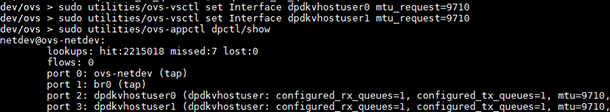
Increase the MTU for the dpdkvhostuser ports to 9710B (max supported mtu_request).
ovs-vsctl set Interface dpdkvhostuser0 mtu_request=9710

	ovs-vsctl set Interface dpdkvhostuser1 mtu_request=9710
Check the bridge to verify that the MTU for each port has increased to 9710B, as per Figure 18.
ovs-appctl dpctl/show
Additional Guest Configuration
In each VM, increase the MTU of the relevant network interface to 9710B, as per Figure 19 and Figure 20.
ifconfig eth1 mtu 9710

	ifconfig eth1 | grep mtu
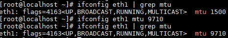
ifconfig eth2 mtu 9710

	ifconfig eth2 | grep mtu

Start the iperf3 server in VM2 and kick off the client in VM1, as before. Observe now that throughput has doubled, from its initial rate of ~7 Gbps to 15.6 Gbps (Figure 21: guest iperf3 transfer rates using 9710B MTU).
Conclusion
In this article, we have described the concept of jumbo frames and observed how they may be enabled at runtime for DPDK-enabled ports in OvS. We’ve also seen how packet buffer memory is organized in OVS DPDK and learned how to set up and test OVS DPDK jumbo frame support. Finally, we’ve observed how enabling jumbo frames in OVS DPDK can dramatically improve throughput for specific use cases.
About the Author
Mark Kavanagh is a network software engineer with Intel. His work is primarily focused on accelerated software switching solutions in user space running on Intel® architecture. His contributions to Open vSwitch with DPDK include incremental DPDK version enablement, Jumbo Frame support3, and TCP Segmentation Offload (TSO) RFC4.
References
- 6000B IP packet + 14B L2 header + 4B L2 CRC