Description
In this example application, you'll learn how to interact with the Terasic* DE10-Nano board's digital I/O:
- 8 green user LEDs
- 4 slide switches
- User push button
The peripherals used to drive the LEDs, and read the switch settings are implemented as “soft” GPIO peripherals within the FPGA. This simple FPGA design illustrates how programmable logic can be used to extend the peripheral set available to a processor. In this case, we added more GPIOs, but we could have added more UARTs, SPI controllers, Ethernet ports, or some combination of each.
Software running on the CPU interacts with these peripherals using the Linux* general-purpose input/output (GPIO) framework. This article walks you through the process of reading from, and writing to those peripherals using the Linux GPIO framework.
Level: beginner.
Materials Needed
- Terasic DE10-Nano kit
The Terasic DE10-Nano development board, based on an Intel® Cyclone® V SoC FPGA, provides a reconfigurable hardware design platform for makers, IoT developers and educators. You can buy the kit here.
- Virtual Network Computing (VNC) client software
A VNC client application running on your host PC is used to remotely control the DE10-Nano board (which is running a VNC server application). If you don’t already have one, there is a link to a free download on the Software Utilities section of the Downloads page.
If you've already visited the ‘Play’ page of the web site served by the board, then you've probably interacted with the 8 user LEDs. The “Blink the LEDs” example on that page provides a simple web interface to turn ON, turn OFF, or blink the LEDs. You may be curious to learn what's happening behind the scenes of the demo application and we'll explore that in this example application tutorial.
Setup Steps
Follow the steps below to prepare your board to build and run the sample applications.
- Open VNC Viewer
- Start a session with VNC* Viewer and type the DE10-Nano board's IP address: 192.168.7.1

Note If you attempt to connect and a black screen appears, power cycle the board.
- Navigate to the examples folder.
a. Double-click the File System icon on the desktop.
b. Locate the examples folder and double-click to open.

c. Open the GPIO example folder, which contains a sandbox folder (code you can play with), and a tar ball version of the sandbox folder in case you need to restore the original.
Note There are three folders containing example design software for the DE10-Nano board; one for the GPIO, one for the FFT, and one for the accelerometer (adxl).
- Sandbox subfolders.
- Open the sandbox folder which contains three subfolders:
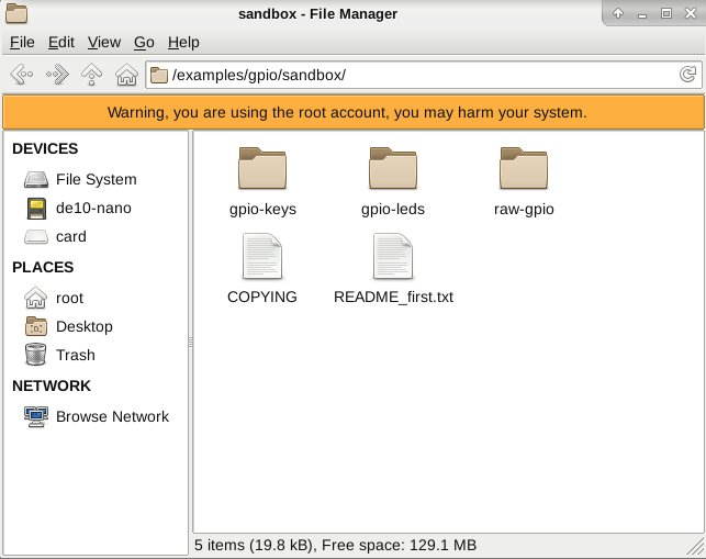
- README text file (optional).
Each of these folders contains example applications, scripts, and a README text file which describes how the examples make use of the Linux GPIO framework to interact with the board hardware.
To view the README_first.txt file:
a. Right-click on README_first.txt.
b. Select Open With.
c. Choose one of the two editors - Vim or gedit.

The READMEfirst.txt file describes the contents of each of the subfolders, and describes the examples contained in each. Here’s what you will see if you open the file with gedit:
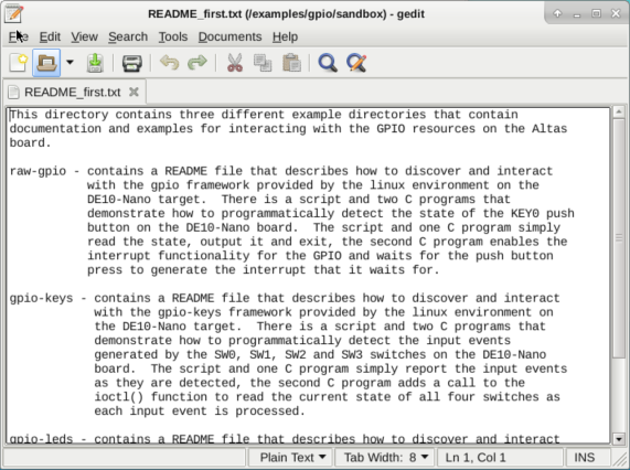
Close the file.
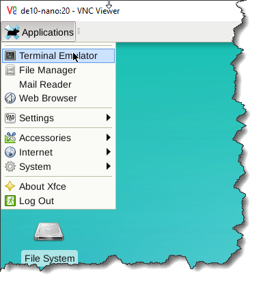
- Open a terminal emulator.
To interact with the board hardware, we are going to use a terminal emulator. Open terminal emulator on the Linux desktop as follows:
a. Click the Applications button at the top of the desktop.
b. Select Terminal Emulator.
gpio-leds
Let’s start by playing with the 8 user LEDs on the board.
Navigate to the gpio-leds folder by typing the following command in the terminal window:
cd /examples/gpio/sandbox/gpio-leds/
This directory contains some example code to toggle the LEDs on the DE10-Nano board. Two versions are provided, a shell script (toggle_fpga_leds.sh) and C program (toggle_fpga_leds.c). Both perform the same function.
Build the 'toggle_fpga_leds' Application
To build the 'toggle_fpga_leds' application type the following command in the terminal window:
./build_toggle_fpga_leds.sh
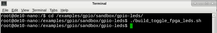
The script compiles the 'toggle_fpga_leds.c' source file and produces the executable 'toggle_fpga_leds' application. If you'd like to learn more about how the script and C program work, open them using the text editor.
Run the Application
Once you've built the application, you can run either the script or the compiled application by typing the following commands into the terminal window:
- To run the script, type: ./toggle_fpga_leds.sh
- To run the compiled application, type: ./toggle_fpga_leds
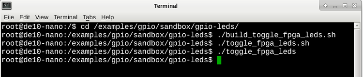
Pay attention to the LEDs on the board! Watch them turn on and off (in sequential order). Both the C program application and script will exit automatically after turning each LEDs on then off.
If you'd like to learn more about how the script and c program work, refer to shell script source file and the C program source file. To learn more about how the Linux gpio-led framework works, open the README_gpio-leds.txt file using the text editor.
More Fun: Control the LEDs
You can also control the LEDs from the terminal window by writing to the ‘brightness’ files generated by the gpio_led framework.
- Turn LED (0) ‘on’ by typing the following command into the terminal window:
echo 1 > /sys/class/leds/fpga_led0/brightness - Turn LED (0) ‘off’ by typing the following command into the terminal window:
echo 0 > /sys/class/leds/fpga_led0/brightness - Try typing a series of commands to turn on every other LED.
- Query the status of LED (0) typing the following command into the terminal window:
cat /sys/class/leds/fpga_led0/brightness
gpio-keys
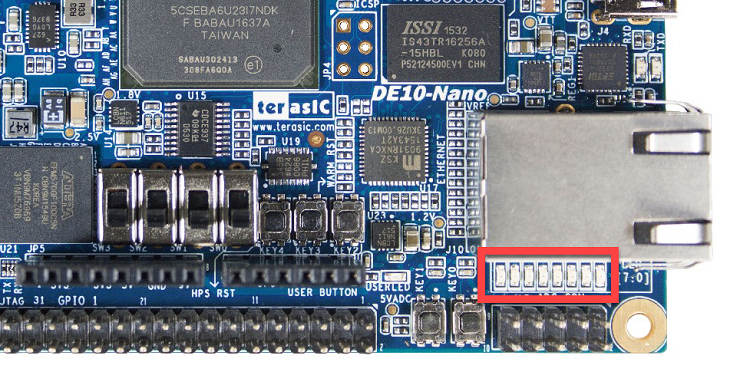
Next we’ll play with the gpio peripherals connected to the slide switches.

With the terminal emulator navigate to the gpio-keys folder by typing the following command into the terminal window.
cd /examples/gpio/sandbox/gpio-keys/

This directory contains an example application that reads the slide switches and reports their status (0 or 1). Just like the LEDs example, there is both a script ('watch_switch_events.sh') and C source file ('watch_switch_events.c') which accomplish the same task.
Build the 'watch_switch_events' Application
To build the 'watch_switch_events' application type the following command in the terminal window:
./build_watch_switch_events.sh
The script compiles the 'watch_switch_events.c' source file and produces the executable 'watch_switch_events' application.

Run the Application
Once you've built the application, you can run either the script or the compiled application by typing the following commands into the terminal window:
- To run the script, type: ./watch_switch_events.sh
- To run the compiled application, type: ./watch_switch_events
While the program is running, slide the switches SW0, SW1, SW2 and SW3 on the DE10-Nano board and notice the output in the terminal window.

The program (and script) monitor the gpio-keys device registered in the system, and print out the input events that they receive from the system. To terminate the script or programs just type CTRL-C on the console that you launched them from.
If you'd like to learn more about how the script and c program work, refer to shell script source file and the C program source file. To learn more about how the Linux gpio-led framework works, open the README_gpio-keys.txt file using the text editor.
More Fun: Reading the Switch States
The ioctl version of the program will additionally print out the current state of all the switches at each input event. Build the 'watch_switch_events_ioctl.c' application by typing the following command:
./build_watch_switch_events_ioctl.sh
Run the application by typing:
./watch_switch_events_ioctl
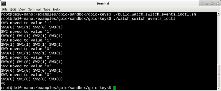
Notice the output as you slide the switches back and forth. To terminate the script by typing CTRL-C. Refer to the C program source file for more details on how it works.
raw-gpio
Finally, we’ll play with the gpio peripherals connected to user push button 0.

With the terminal emulator navigate to the raw-gpio folder by typing the following command:
cd /examples/gpio/sandbox/raw-gpio/
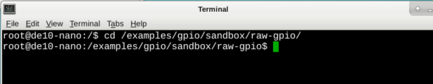
This directory contains an example application that reads the state of push button 0 and reports their status (0 or 1). Just like the previous examples, there is both a script ('show_KEY0_pb_state.sh') and C source file ('show_KEY0_pb_state.c') which accomplish the same task.
Build the 'show_KEY0_pb_state' Application
To build the 'watch_switch_events' application type the following command in the terminal window:
./build_show_KEY0_pb_state.sh
The script compiles the 'show_KEY0_pb_state.c' source file and produces the executable 'show_KEY0_pb_state' application.

Run the Application
Once you've built the application, you can run either the script or the compiled application by typing the following commands into the terminal window:
- To run the script, type: ./show_KEY0_pb_state.sh
- To run the compiled application, type: ./show_KEY0_pb_state
Run the program several times, with the push button pressed and released, and notice the output in the terminal window.
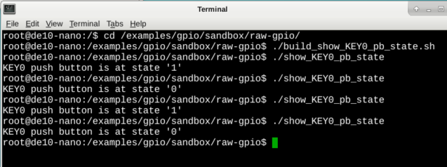
The program and script read a file associated with the push button 0 and report the state.
If you'd like to learn more about how the script and c program work, refer to shell script source file and the C program source file. To learn more about how the Linux gpio-led framework works, open the README_gpio.txt file using the text editor.
More Fun: Detect the Push Buttons
The C program called 'poll_KEY0_pb_state.c' adds a poll() call to the 'show_KEY0_pb_state.sh' program to demonstrate the interrupt functionality provided by the gpio framework to detect the push button press via a hardware interrupt.
Build the 'poll_KEY0_pb_state.c' application by typing the following command:
./poll_KEY0_pb_state.sh
Run the application by typing:
./poll_KEY0_pb_state

Notice that the interrupt enabled version of the program waits until the button is pressed before reporting the action and terminating.
Refer to the C program source file for more details on how it works. To learn more about how the Linux gpio-led framework works, open the README_gpio.txt file using the text editor.