Introduction
Overview
This guide provides the information required to become familiar with the Intel® Quark™ SoC S1000 ASIC firmware infrastructure components and principles of operation.
Audience and Purpose
This document is intended for audio firmware engineers integrating algorithms on Intel Quark SoC S1000 ASIC.
Terminology
| Term | Description |
|---|---|
| ADSP | Audio DSP |
| Canonical format | 32-bit MSB samples |
| DMA | Direct Memory Access |
| DMIC | Digital Microphone (PDM Mems) |
| DP | Data Processing (EDF scheduled tasks) |
| DSP | Digital Signal Processing |
| EDF | Earliest Deadline First |
| Endpoint | Device associated with gateway |
| FW | Firmware |
| Gateway | Unidirectional (input OR output) DMA gateway |
| Graph | Set of pipelines |
| IPC | Inter-Process Communication |
| Library | Dynamically loadable set of the modules |
| LL | Low Latency (1ms, 0.33ms-8ms considered) |
| Loadable module | Dynamically loadable module |
| Management service | A service in FW that manages the communication, configuration, and processing pipelines. |
| Module | Processing component |
| Pipeline | Linear chain of modules |
| Queue | Both Sink and Source |
| RT | Real Time (works as prefix) |
| Sink | Interface for write operation |
| Source | Interface for read operation |
| SW | Software |
| SysTick | System Tick, main interrupt asserted every LL |
Reference Documents
| Document | Document Number / Revision |
|---|---|
| Intel® Quark™ S1000 ASIC Datasheet | 570159 |
Intel® Intel® Quark™ SoC S1000 ASIC Architecture Overview
The Intel Quark SoC S1000 ASIC offers the ability to do far-field speech recognition in various smart devices. The Intel Quark SoC S1000 ASIC is designed for complex far-field signal processing algorithms that use high dimensional microphone arrays to do beamforming, cancel echoes, and reduce noise. A pair of DSPs, a neural network accelerator, internal memory, and a set of I/Os provide the necessary resources for speech processing solutions.
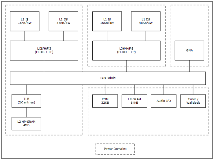
Figure 1. Intel Quark SoC S1000 ASIC High-Level Block Diagram
Note For full technical specifications, see the Intel Quark SoC S1000 ASIC Datasheet.
System Model
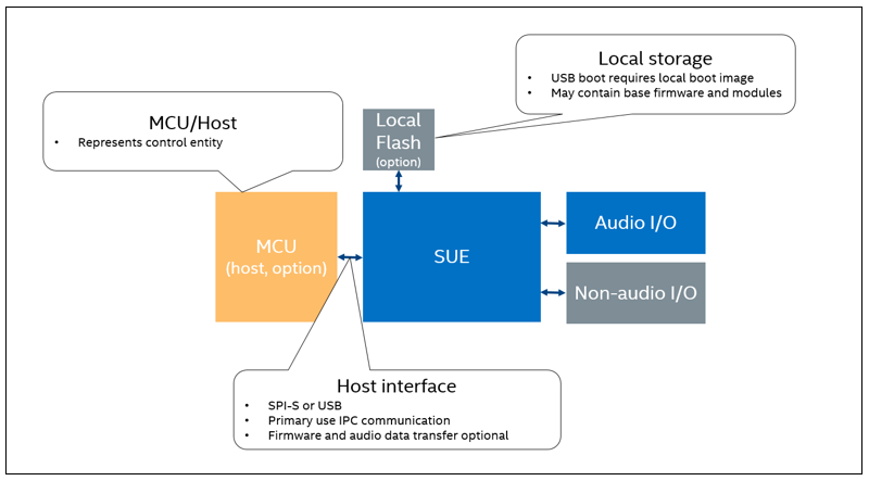
Figure 2. System Model
IPC Communication Over SPI-S
SPI is a protocol that is fully controlled by the master of the SPI bus. The Intel Quark SoC S1000 ASIC is a slave on the SPI bus. Therefore, it cannot initiate any bus transactions or perform flow control when the master performs a transaction.
The DSP in the Intel Quark SoC S1000 ASIC gets notifications of received data only when a receive transfer is configured a priori by the DSP. That is, to get notifications of received data when the threshold is exceeded, the DSP firmware must program a specific data size threshold up front.
The DSP can prepare a response and setup for transfer to the Host, however, the transfer can only be initiated by the Host that is the master on the SPI bus.
The DSP indicates SPI-S readiness by asserting IRQ high. The Host may only start the transfer after a rising edge is observed on the IRQ. The Host may not initiate a transfer when the IRQ is deasserted.
To perform an asynchronous notification, the DSP toggles IRQ line by deasserting it low for minimum 1µs. The notification message (payload) is transmitted as a response when the master performs an SPI transfer on receiving the notification.
IPC Protocol
The IPC protocol defaults to the short version of the message called IPC64 that is 64 bytes long. This mode assumes the use of SPI-S IP FIFO to store transmitted data.
On explicit request, IPC64 protocol may be switched to IPC4K protocol. This allows a 4KB IPC transfer in one or both directions.
Note The ROM does not support IPC4K message protocol.
IPC64 Protocol
The IPC64 protocol is default after initialization, and after any other transfer that does not select an alternative protocol.
IPC64 uses SPI-S RX FIFO and FIFO full interrupt to receive data.
IPC64 uses SPI-S TX FIFO to store IPC response data. Data is placed into FIFO before transaction state.
Note ROM implementation of IPC64 uses polling instead of interrupts.
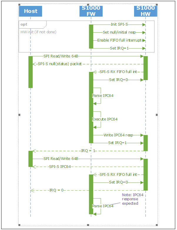
Figure 3. IPC64 Protocol
Receive routines on both the host and DSP side must be ready to receive a “null” message containing all zero bits in the first 32 bits of the message. A null response sent from DSP may have the RSP bit set (optionally). Since behavior may vary between messages, the host should accept both forms of the message.
If the DSP side has nothing more to send, it must post a “null” message and rise IRQ. This action is required to enable the host to perform a transaction, if required.
To enter protocol idle state, the host side must ignore this interrupt. To differentiate between interrupts/states, the host shall not initiate a transaction after receiving a “null” status in response to a “null” request. If host attention is required, the DSP side must toggle IRQ once again.
Note Although starting a transaction while IRQ is 0 violates the defined protocol, the host is not required to actively track this signal. In this case, setting IRQ to 0 by DSP is not related to the fact that data for transmission is not ready. It is necessary only to create the rising edge of the IRQ signal.
IPC4K Protocol
IPC4K protocol is selected via IPC 4K mode IPC. IPC4K IPC mode selects the direction of transfer via flags.
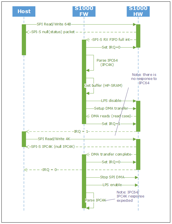
Figure 4. IPC4K Protocol
IPC4K protocol may be selected for single or multiple transfers. There is no response to protocol switch IPC. Also, the IPC4K response format depends on the format selected for the next IPC. By default, this format is IPC64.
IPC4K uses a DMA buffer pre-allocated in HP-SRAM (LP-SRAM is size constrained). Since LP-GPDMA cannot wake the HP domain, the IPC routine must prohibit the use of LPS for the time that DMA is armed (HP domain power gating).
Receive routines on both host and DSP side must be ready to receive a “null” message containing all zero bits in the first 32 bits of the message. The response size must adhere to the currently selected format. A DSP request to switch to IPC4K must, in all cases, prepare an IPC4K response. It may be any of the following:
- IPC4K null packet (assume that hardware supports this function)
- IPC4K data packet that was scheduled for transmission to Host
- IPC64 packet placed into IPC4K DMA buffer and padded with zeros
Note This assumption is made to avoid FIFO underrun from an IPC64 packet being sent in an IPC4K transaction. An underrun that cannot be differentiated from other underrun cases is not acceptable, as it would prevent diagnosis of actual issues.
Byte Packing/Byte Order Assumptions
IPC communication over SPI-S uses plain (no designated fields) bit transfer. The receive/transmit FIFOs are 32 bits wide. Bytes within a 32-bit word are transferred starting from MSB.
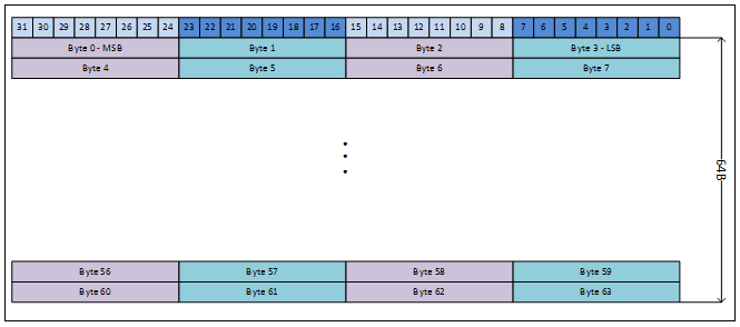
Figure 5. Byte Ordering - IPC64 Example
Certain SPI-M controllers may not be able to generate raw transactions, or transactions that are 64 bytes long. For such hosts, you can send IPC message in portions with the following assumptions:
- Each transaction frame (assertion of SS signal) must be a minimum of 32-bits or a multiple of 32-bits
- The number of bytes must match the expected transfer size
- No padding between transactions, all data is valid on both transmit and receive
To allow operation both with and without toggling the slave select signal during frame transfer, the slave controller uses mode 3 as default.
Figure 6 contains examples of data formatting from a controller that supports command, address fields, and 32-bit data. To keep 32-bit alignment, the example shows an 8-bit command and a 24-bit address, followed by various 32-bit wide data values.

Figure 6. SPI Data Layout Example — Command, 24-bit Address, and 32-bit Data
Depending on the number of supported data values, the transaction may need to be repeated multiple times. If only a single 32-bit value is supported, the host must generate eight 64-bit SPI transactions to send IPC64.

Figure 7. SPI Data Layout Example — Command, 24-bit Address, and 16-bit Data
Figure 7 depicts a similar case, with 16-bit long data values. An even number of data transactions is required (two, at minimum) to keep 32-bit alignment.

Figure 8. SPI Data Layout Example — Command, 24-bit Address, and 8-bit Data
Figure 8 differs only in the payload size. Here, the data is only one byte long. To keep the transaction, four data cycles or a multiple of four is required.

Figure 9. SPI Data Layout Example — Command, 8-bit Address, and 16-bit Data
Figure 9 shows an example of generating IPC with a simple host controller that can send only 32-bit transactions. The example uses a command, 8-bit address, and 16-bit data to create a 32-bit transaction. A separate transaction generates each 32-bit message data.

Figure 10. SPI Data Layout Example — Command, 16-bit Address, and 8-bit Data
The example in Figure 10 differs in field partitioning. The example uses a command, 16-bit long address, and 8-bit long data.
Depending on the capabilities of the host controller, other combinations are possible. In all the provided examples, the controller must be able to capture data while sending command and address bytes.
IPC64/IPC4K Message Format
IPC communication over SPI must be adapted to media-specific requirements. The design goal is to minimize the change scope and allow transparent translation messages in lower level of firmware and software.
IPC specifics include:
- Must use predefined (announced earlier message size)
- Must advertise message size to remote side
- Asynchronous notification method
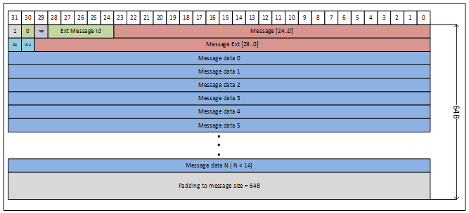
Figure 11. IPC64 Generic Message Format
Figure 11 depicts a generic IPC64 message. The low-level routine that transmits the message must ensure that the size of the message submitted to SPI hardware is exactly 64 bytes. If required, the low-level routine shall add padding (filled with zeros) to achieve the required size.
R4 and W4 bit fields are used to reduce transmission overhead. Both fields reuse B/E fields that are not used in a given version of the protocol. The R4 field requests the DMA buffer setup for SPI Read. For a master transaction initiated from the host, this means that the subsequent transaction is expected to read a 4KB message. The same field in the response message indicates to the SPI master a request for a 4KB transaction (for example, to return a long message response). Similarly, the W4 field defines the buffer transaction setup in the opposite direction.
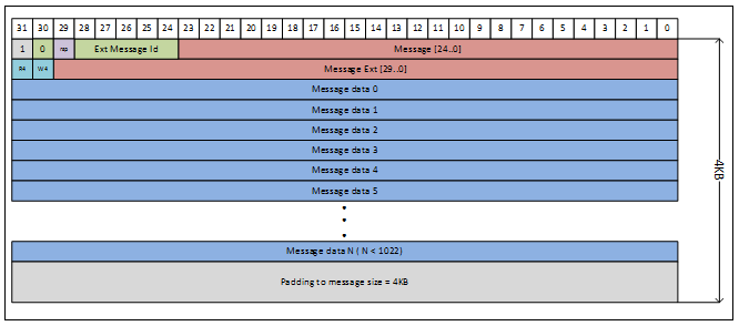
Figure 12. IPC4K Generic Message Format
The format of a 4KB message is shown in Figure 12. The only difference in this situation is the amount of allowed payload or required padding.
The protocol allows independent setting of the R4 and W4 fields. However, if one bit is set, the host performs a 4KB R/W transaction. This means that an unselected buffer must either be disabled (null transfer), or adhere to the selected format.
A similar situation occurs when both the R4 and W4 bits are set. In this situation, a 4KB transfer is executed in both directions.

Figure 13. IPC Mode Select IPC
The explicit message IPC Mode Select (Figure 13) is used when the host or device must switch to 4K mode without data for transmitting/receiving. IPC Mode Select is essentially a “null” IPC64 message that allows mode selection for the next transaction. The message can be used in both directions. Specifically, the SPI slave may choose to return this message to indicate that the returning data requires a larger buffer.
IPC Mode Select IPC with both R4 and W4 messages is used as a “null” message. It is useful for the host to pull a pending message from SPI-S hardware.
Note In general, the master side shall request IPC4K transfers for transactions expected to return more than 60 bytes of data.
Note Intel recommends that you fit asynchronous notification data in IPC64 format. Otherwise, notification handling may require three messages.
Asynchronous Notification Support
Asynchronous notification requires the generation of a minimum of two interrupt events using the IRQ line.
During the first interrupt, the host transfers previously a configured (typically null) response according to selected protocol. In a typical case (idle/waiting for event scenario), the hardware IPC selects IPC64 protocol version.
This approach is required because, once firmware determines the need for an asynchronous response, the “current” (typically empty) response is already submitted to hardware. Since hardware does not allow the safe substitution of a response, the firmware must force a flush of the current response.
Since the host is expected to be idle at a time when asynchronous notification is received, it issues IPC Mode Select IPC.
Note The host may choose to request IPC64 mode (the default and recommended mode), or IPC4K mode (if majority of notifications are expected to be in IPC4K format).
The firmware parses the received data to determine the next transaction buffer size. In a typical case, the firmware submits an IPC64 response. However, as the host may choose IPC4K format, the firmware must also handle the case of sending an IPC64 response in the 4K buffer.
Yet another case is created when the upper firmware layers request the IPC4K notification format (message size >60 bytes), while the host selects IPC64 mode. To handle this situation, the firmware responds with IPC Mode Select, with the R4 field set, to force the host to select 4K mode.
Independently of the previous case, the firmware attempts to put response data and rise interrupt over the IRQ line, as long as asynchronous notification data remains unsubmitted.
Intel recommends that the host suppresses sending messages while previous operations are incomplete. Although such concurrency cannot be eliminated, both sides of the protocol must handle messages asynchronously. Specifically, the host must not block forward receive progress while waiting for a request response, because the asynchronous notification inserted in front of the expected response must be comprehended.
Host State Machine
Figure 14 shows the host state machine. After deasserting, a reset triggers ROM to put a status message in the RX FIFO. To read the message, the host must either send some message. Typically, this message is a null message that allows determination of the SoC version (status). For clarity, the figure does not include opportunistic transfers that may happen on both sides, nor does it include IPC format selection.
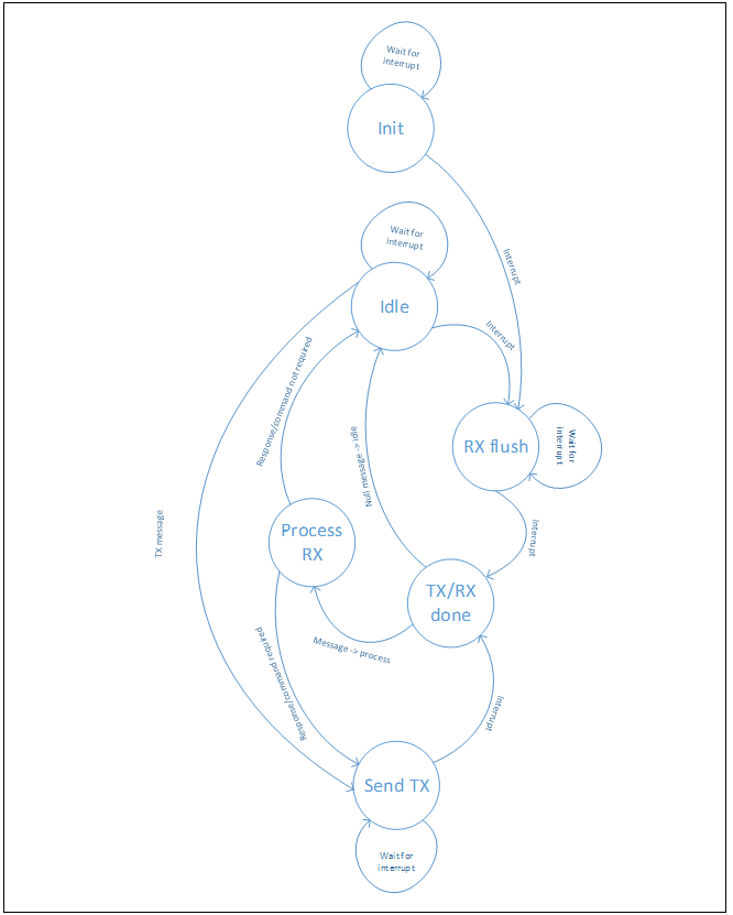
Figure 14. Host State Machine
Flows
Boot Options
SPI-S Mode Operation
Boot from SPI-S is used in configurations where the firmware for the Intel Quark SoC S1000 ASIC is downloaded from a host. This configuration does not usually have a flash memory attached to the SPI-M of the Intel Quark SoC S1000 ASIC.
SPI-S Mode Selection
SPI-S mode is selected by asserting high (statically or dynamically) strap option connected to SPI_SLAVE_MST_N_BOOT. The Intel Quark SoC S1000 ASIC samples the strap during de-assertion of the HOST_RST_N input. If the sampled strap value is 1, the ROM code attempts to initialize the SPI-S controller and start polling for messages from the host.
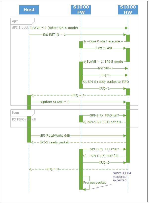
Figure 15. Interactions Between Host and Intel Quark SoC S1000 ASIC in SPI-S Mode
Figure 15 shows the SPI-S mode support. After early initialization and boot mode detection, the firmware enters a wait loop for the initial IPC64 command packet. Once the RX FIFO ready state is determined, the firmware starts reading the necessary DWORDs from the FIFO. By reading the first one or two DWORDs, the ROM implementation can determine and properly dispatch the command.
IPC Protocol
The defined messages use the Count field to indicate the number of message DWORDS present after the header. The IPC message send function provides padding between the current message size, (Count+2)*4, and the currently selected IPC mode. The IPC processing function consumes the padding DWORDs from the SPI-S FIFO. In the current definition, the ROM supports IPC64 messages only.
ROM Ready IPC
As part of early boot process ROM, puts ROM Ready IPC in SPI-S TX FIFO. The message indicates that the ROM is ready to receive IPC commands, and provides information about the ASIC version.

Figure 16. ROM Ready IPC
Firmware Load Messages
Regardless of framing, the payload is expected to contain only data up to the number of messages defined in the Image Size field. The address field is expected to reside in HP-SRAM. The memory address and image size must be aligned to a minimum of 64B.
The image offset field is not used in SPI-S mode. Set it to 0.
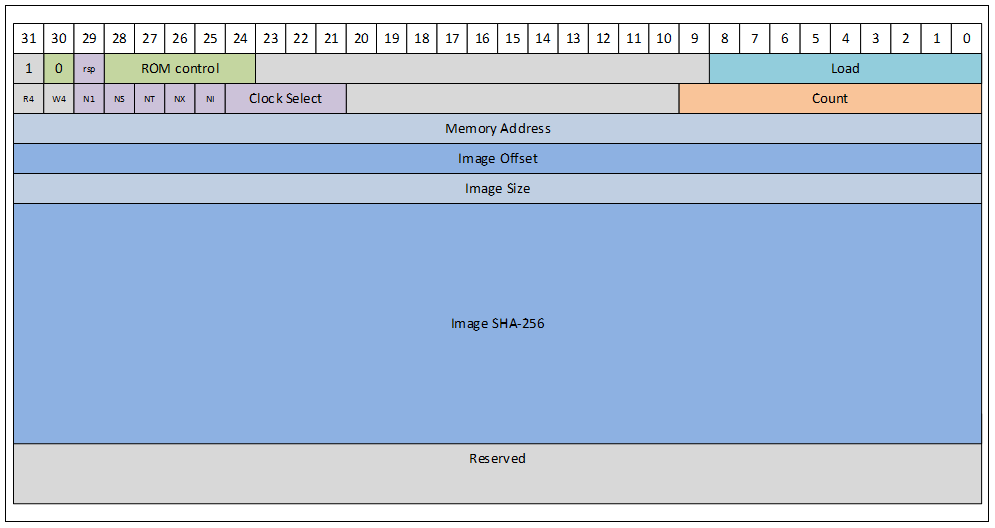
Figure 17. Load Firmware IPC
By default, the message carries the valid Memory Address, Image Size, and SHA-256 checksum of the image.
All N* fields are reserved and shall be set to 0.
The Clock Select field allows the host to select an alternative SPI-S clock source. The currently defined encodings are as follows:
- 0 – use default clock
- 1 – use high-performance clock
All other values for this field are reserved.
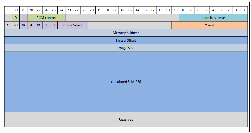
Figure 18. Load Firmware Response IPC
The Load Firmware response IPC is placed in the TX FIFO of the controller. It contains a copy of the original IPC with the RSP bit set, and an updated SHA-256 value.
The firmware entry point is the same as the load memory address. This allows maximum flexibility of internal image implementation.
SPI-M Mode Operation
Boot from SPI-M connected flash is used in configurations where the Intel Quark SoC S1000 ASIC is operating independently or with the host connected via USB/SPI-S. In these configurations, a valid firmware image must be stored in the connected flash from which the Intel Quark SoC S1000 ASIC can boot.
SPI Part Assumptions
To boot successfully, the SPI slave device (presumably a non-volatile memory type) must meet the following criteria:
- Connection SPI-M interface of Intel Quark SoC S1000 ASIC as slave #0
- VIO 1.8V, SPI clock min 19.2MHz
- Support mode 0 (ROM uses mode 0)
- Support read command 3 with 24-bit address and w/o need for dummy cycles
- Support for linear read burst (no size constrains)
Boot Mode Selection
Select SPI-M mode by platform driving (pulling down) the SPI_SLAVE_MST_N_BOOT signal low before HOST_RST_N is deasserted.
Boot in SPI-M Mode
Figure 19 depicts the interactions between firmware (in ROM) and hardware.
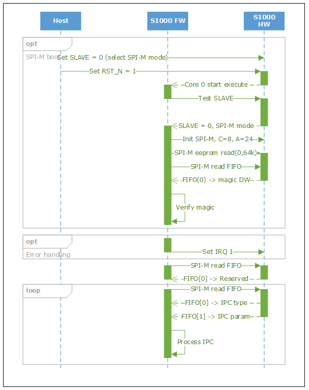
Figure 19. Boot From Locally Attached SPI Device
SPI Memory Layout
The initial portion of flash is organized as a linear block of DWORD values. Starting from address 0, DWORD values can be read one by one and processed sequentially. This approach simplifies the ROM interpretation routine that must be assembly coded (SRAM is not available during initial parsing).
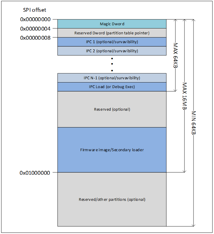
Figure 20. SPI Memory/Flash Layout
Figure 20 depicts the SPI memory (Flash) layout, as interpreted by ROM.
The SPI memory starts from the magic DWORD (0x30504353, the value used if flash is attached and programmed). This magic DWORD mechanism differentiates between a valid image and an invalid image, and takes fallback action if the image is invalid.
Next there is a single DWORD, not parsed by ROM. This DWORD is intended to be the partition pointer/flash file system pointer. In the example in Figure 21, the pointer references the partition table at 64 KB offset. This type of organization allows you to keep some reserved space for the hardware initialization or loader portion of the flash, and to update it without repartitioning the entire device. The pointer is used by the secondary loader to quickly locate the table without parsing the initial portion of the flash again.
After the two initial DWORDs, the IPC script starts. The entire script, including the initial DWORDs and Load command, fits in 64KB.
The minimum configuration is just 64B: 8 bytes of initial words, and a 56 byte load command.
The firmware image or secondary loader image is located entirely in the first 16 MB of SPI space.
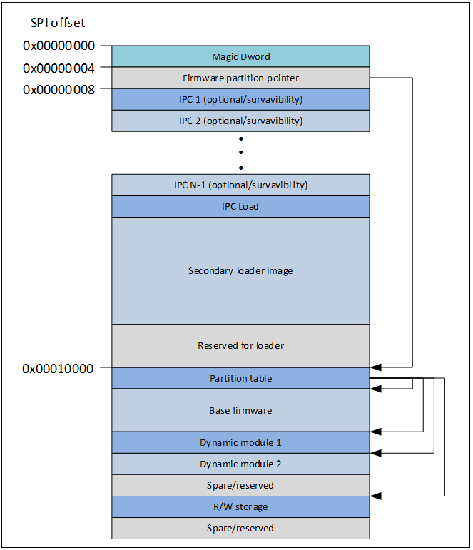
Figure 21. Memory Partitioning Example
IPC Protocol
Firmware Load Messages
Regardless of framing, the payload is expected to contain only data up to the number of messages defined in the Count field. By default, the Address field is expected to reside in HP-SRAM. The Memory Address and Image Size must be aligned to a minimum of 64B.
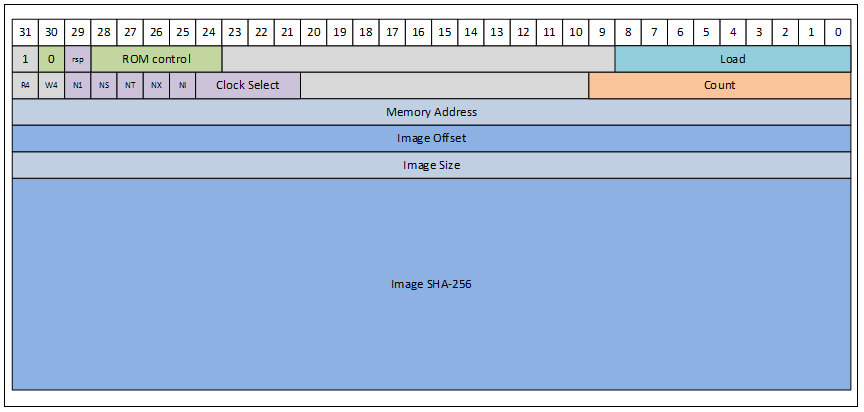
Figure 22. Load Firmware IPC
By default, the message carries a valid memory address, DWORD aligned image size, and SHA-256 checksum of the image.
All N* fields are reserved and shall be set to 0.
The Clock Select field selects an SPI-M clock source and divider to be used during firmware load.
The currently defined encodings are as follows:
- 0 – Use default clock
All other values of this field are reserved.
If there is SHA-256 hash check failure, the ROM enters a fatal error state.
Creating Streams
To create a stream, the management service must build the list of module instances that will be part of the stream processing logic. Each module instance affinity must be assigned to a core by the management service. If any instance that is on the list requires a loadable module to be available, the management service must check if the module is already loaded. Otherwise, it must execute the module loading flow before sending the module instance list to the firmware. The firmware expects that all resources, including processing code, memory, and core bandwidth, are verified by the management service before the module instance list arrives.
A stream may consist of one or more pipelines. The firmware supports up to four pipelines connected via Mixers in a single render stream. Each pipeline is a sequence of module instances. Each module instance may execute in either Low Latency or Data Processing domain. Each subsequence of consecutive Data Processing module instances must be assigned to the same Core.
For example, a pipeline that consists of the following module instances LL0-LL1-DP2-DP3-LL4-DP5-DP6-LL7 must be distributed among the cores so that the subsequence DP2…DP3 has the same affinity (for example, Core0) and DP5…DP6 also has the same affinity (for example, Core1).
Note Modules must be instantiated in their data processing order within the pipeline. That is, if mod1 produces data for mod2, then IPC Init Instance (mod1) must be called before IPC Init Instance (mod2).
Retrieving FW/HW Configuration and Topology Information
The management service may query firmware and hardware configuration, and topology information, by requesting the values of the following parameters:
- Base FW parameters:
- Firmware Config
- Hardware Config
- Modules Info
- Pipeline List Info
- Pipeline Properties
- Module Instances Info
- Gateways Info
- Memory State Info
- Power State Info
- Module instance parameters:
- Module Instance Properties
The management service may also set some of the firmware configuration parameters.
Retrieving Performance Data
Performance data collecting is disabled by default in the firmware.
To retrieve capture performance data, the management service must execute following steps:
- Enable performance measurements by setting Base FW’s PERF_MEASUREMENTS_STATE parameter to either Stopped or Started (in the latter, data collecting starts immediately).
- Start performance measurements by changing the state to Started (if not done in the previous step).
- Execute the scenario to be measured.
- Pause performance measurements by changing state to Paused. Changing the state to Stopped erases all collected data immediately.
- Retrieve performance measurements data, including global items provided by the Base FW’s GLOBAL_PERF_DATA parameter, and the pipeline and module instance properties.
- Now, performance measurements may be either resumed (Paused → Started), restarted (Paused → Stopped → Started) or disabled completely (Paused → Disabled).
To see all possible transitions between states of performance data collection mechanism, refer to Introduction.
Fatal Error Reporting
The DSP ROM implements a fatal error handling mechanism. All unexpected errors, such as L1 or L2 double-bit errors, result in firmware halt and set the IRQ line to 1. More detailed reasons can be determined only using JTAG.
If the firmware is not responsive, the host-based software must reset the Intel Quark SoC S1000 ASIC by asserting the HOST_RST_N pin low.
IPC Interface
The IPC interface enables message exchange between firmware and the software running on host.
IPC communication may be initiated by either side, as follows:
- The management service sends an IPC request – either a Global message directed to the firmware infrastructure (Base FW), or a Module message directed to a module instance running in firmware – and the firmware replies with an IPC response.
- Firmware sends an IPC Notification (one way, not replied to by the host) that is a Global message of NOTIFICATION type.
An IPC message consists of a header exchanged through SPI interface, and an optional payload.
It applies to the following IPC messages:
- Load Module
- Unload Module
- Init Module
- Large Config Set
- Large Config Get
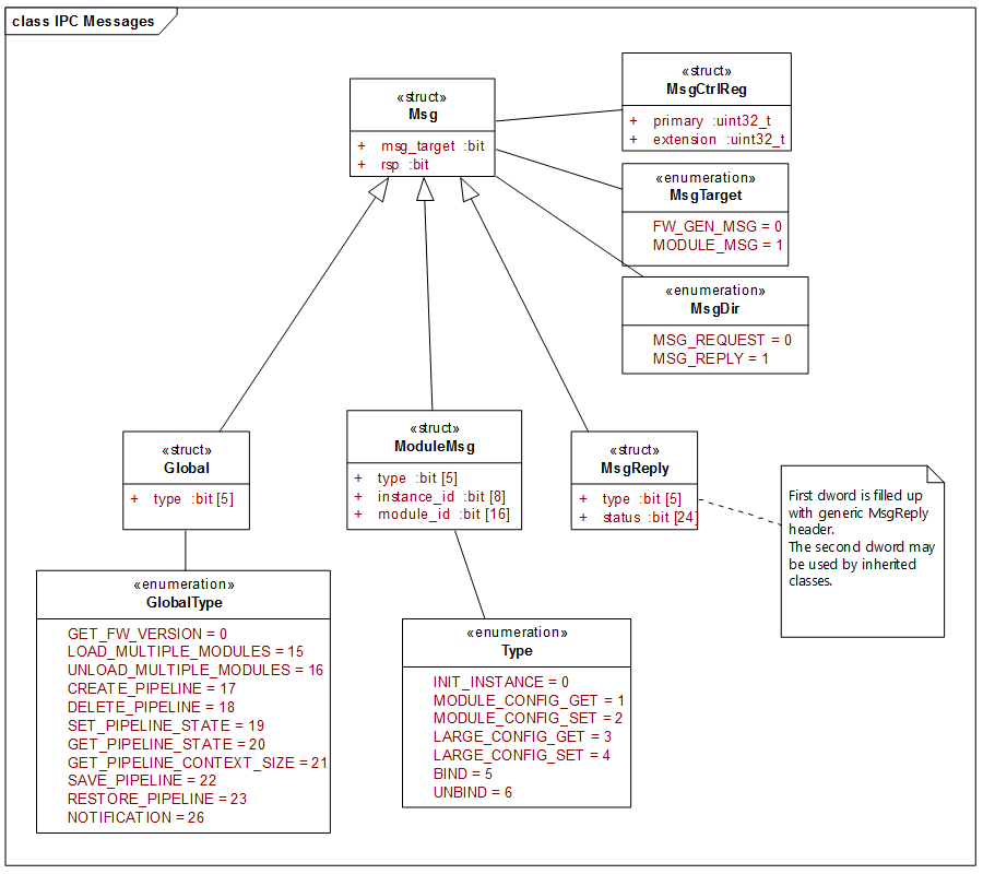
Figure 23. IPC Message Header
There are three types of IPC message headers:
- Global Message – a request from the management service directed to the firmware infrastructure
- Module Message – a request from the management service directed to one of firmware module instances
- Message Reply – a reply to the management service sent by the firmware in response to either request
IPC Base Structures
MsgCtrlReg Structure
Note The Msg structure and all derived structures preserve the upper level bit definition. The Msg structure breaks down MsgCtrlReg::payload_primary and MsgCtrlReg::payload_extension, preserving other fields of MsgCtrlReg. Derived messages break down Msg::Bits::rsvd0 and Msg::Bits::rsvd1, preserving other fields of Msg::Bits.
struct MsgCtrlReg
{
    union
    {
        struct
        {
            uint32_t primary;
            uint32_t extension;
        } dw;

        struct
        {
            // primary register fields

            uint32_t payload_primary   : 31;
            uint32_t _busy             : 1;

            // extension register fields

            uint32_t payload_extension : 30;
            uint32_t _done             : 1;
            uint32_t _error            : 1
        } bits;

    } regs;
};
Msg Structure
This is a base structure for all IPC message headers. It defines common bits that are used in both communication directions.
Syntax
struct Msg
{
    enum MsgTarget
    {
        FW_GEN_MSG = 0, // Global message
        MODULE_MSG = 1  // Module message
    };

    enum MsgDir
    {
        MSG_REQUEST = 0,       // Request
        MSG_NOTIFICATION = 0,  // Notification
        MSG_REPLY = 1          // Reply
    };

    struct Bits
    {
        // primary register

        uint32_t rsvd0      : 29;
        uint32_t rsp        : 1;
        uint32_t msg_tgt    : 1;
        uint32_t _busy      : 1;

        // extension register

        uint32_t rsvd1      : 30;
        uint32_t _done      : 1;
        uint32_t _error     : 1;
    };
};
Members
rsp
Indicates that an upstream message is a response to some request (and not a notification). This bit lets the management service dispatch the message appropriately avoiding a race condition in the following scenario:
- Host sends a request down to FW.
- FW (at the same time sends a notification).
- Host receives upstream message and is able to qualify it as an unsolicited notification rather than a response to the request just sent to FW.
- FW receives a request, processes it and sends a response.
One of MsgDir values.
msg_tgt
Used by FW to dispatch Global (infrastructure directed) messages and messages directed to module instances. One of MsgTarget values.
Global Request
Global::Bits Structure
This structure is a base class for all messages handled by the Base FW.
Syntax
struct Bits
{
    uint32_t rsvd0      : 24;
    uint32_t type       : 5;
    uint32_t rsp        : 1;
    uint32_t msg_tgt    : 1;
    uint32_t _busy      : 1;

    uint32_t rsvd1      : 30;
    uint32_t _done      : 1;
    uint32_t _error     : 1;
};
Members
msg_tgt
Set to Msg::FW_GEN_MSG
rsp
Set to Msg::MSG_REQUEST
type
Indicates type of the Global message (one of Global::Type).
ModuleMsg Request
This structure is a base class for all messages directed to the modules and handled inside the modules. There are some exceptions of module messages that are handled by the Base FW, but this is transparent for host IPC.
Every Module Message specifies the ID of the module and instance to which the message is dispatched.
ModuleMsg::Bits Structure
Syntax
struct Bits
{
    uint32_t module_id      : 16;
    uint32_t instance_id    : 8;
    uint32_t type           : 5;
    uint32_t rsp            : 1;
    uint32_t msg_tgt        : 1;
    uint32_t _busy          : 1;

    uint32_t rsvd1          : 30;
    uint32_t _done          : 1;
    uint32_t _error         : 1;
};
Members
msg_tgt
Set to Msg::MODULE_MSG
rsp
Set to Msg::MSG_REQUEST
type
Indicates type of the Module message (one of ModuleMsg::Type).
instance_id
ID of the target module instance.
module_id
ID of the target module.
MsgReply Response
This structure is a base class for replies sent back to the originator once handling of a request is completed.
Due to the new asymmetric nature of request and response, the status field is now 24-bits wide. Therefore, the first DWORD of the message control register is filled. If message-specific data must be sent back, it may be packed into either the second DWORD or into the Data payload. If there is no message type-specific data to be sent back, the message handler may send a reply of MsgReply type directly. Otherwise, a defined inherited structure is used to construct a reply.
Note Due to the same width and position of the type field in both Global and ModuleMsg requests, you do not need to define separate reply structures. MsgReply may be used for messages of both types.
MsgReply Structure
Syntax
struct MsgReply : Msg
{
    struct Bits
    {
        uint32_t status     : IXC_STATUS_BITS;
        uint32_t type       : 5;
        uint32_t rsp        : 1;
        uint32_t msg_tgt    : 1;
        uint32_t _busy      : 1;

        uint32_t rsvd1      : 30;
        uint32_t _done      : 1;
        uint32_t _error     : 1;
    };
};
Members
msg_tgt
Same as the request target. Either Msg::FW_GEN_MSG or Msg::MODULE_MSG.
rsp
Set to Msg::MSG_REPLY.
type
One of message types.
status
One of IxcStatus values.
Remarks
The MsgReply::status is set by FW to one of IxcStatus values. There is one flat space of status values used by all FW components that reports the status of the operation in the IPC reply.
See the adsp_ixc_status.h header file for the most up-to-date complete documentation. The following sections outline some message-specific status values.
General IPC Error Codes
Table 3. IPC General Error Codes
| Error Code | Value | Description |
|---|---|---|
| ADSP_IPC_SUCCCESS | 0 | The operation was successful. |
| ADSP_IPC_ERROR_INVALID_PARAM | 1 | Invalid parameter specified. |
| ADSP_IPC_UNKNOWN_MESSAGE_TYPE | 2 | Unknown message ID specified. |
| ADSP_IPC_OUT_OF_MEMORY | 3 | No memory to complete the request. |
| ADSP_IPC_BUSY | 4 | System or resource is busy. |
| ADSP_IPC_PENDING | 5 | The request was scheduled for asynchronous processing. |
| ADSP_IPC_FAILURE | 6 | Unknown error while processing the request. |
| ADSP_IPC_INVALID_REQUEST | 7 | Unsupported operation requested. |
| <reserved> | 8 | N/A to SKU2-LP (was ADSP_STAGE_UNINTIALIZED). |
| ADSP_IPC_INVALID_RESOURCE_ID | 9 | Specified resource not found. |
| <reserved> | 10 | N/A to SKU2-LP (was ADSP_SOURCE_NOT_STARTED). |
| ADSP_IPC_OUT_OF_MIPS | 11 | No MCPS to complete the request. |
| ADSP_INVALID_RESOURCE_STATE | 12 | Required resource is in invalid state. |
| ADSP_IPC_UNAVAILABLE | 15 | Requested service or data is unavailable on the target platform. |
General IPC Messages
Static and dynamic runtime FW infrastructure properties are retrieved using module configuration messages addressed to module ID 0 (Base FW). See Section 5.6.4, “Base FW”.
Performance Measurements Command
The management service sends this message to execute the performance measurements command.
Request Message Control Header
struct Bits
{
    uint32_t command        : 8;
    uint32_t rsvd0          : 16;
    uint32_t type           : 5;
    uint32_t rsp            : 1;
    uint32_t msg_tgt        : 1;
    uint32_t _reserved_0    : 1;  // HW ctrl reserved bits

    uint32_t rsvd1          : 30;
    uint32_t _reserved_2    : 2;  // HW ctrl reserved bits
};
Table 4. Performance Measurements Command – Request Parameters
| Field | Value |
|---|---|
| msg_tgt | Msg::FW_GEN_MSG |
| rsp | Msg::MSG_REQUEST |
| type | Global::PERF_MEASUREMENTS_CMD |
| command |
Command to be executed by FW, one of:
|
Input Data
There is no input data.
Reply Message Control Header
struct Bits
{
    uint32_t status     : IXC_STATUS_BITS;
    uint32_t type       : 5;
    uint32_t rsp        : 1;
    uint32_t msg_tgt    : 1;
    uint32_t _busy      : 1;

    uint32_t rsvd1      : 30;
    uint32_t _done      : 1;
    uint32_t _error     : 1;
};
Table 5. Performance Measurements Command – Reply Parameters
| Field | Value |
|---|---|
| msg_tgt | Msg::FW_GEN_MSG |
| rsp | Msg::MSG_REPLY |
| type | Global::PERF_MEASUREMENTS_CMD |
| status |
ADSP_IPC_SUCCESS ADSP_IPC_INVALID_RESOURCE_STATE ADSP_IPC_INVALID_REQUEST |
Output Data
There is no output data.
Library & Module Management IPC Messages
Load Library
The management service sends this message to initiate loading of a library into the ADSP memory.
Request Message Control Header
struct Bits
{
    uint32_t dma_id      : 5;
    uint32_t rsvd0       : 11;
    uint32_t lib_id      : 4;
    uint32_t rsvd1       : 4;
    uint32_t type        : 5;
    uint32_t rsp         : 1;
    uint32_t msg_tgt     : 1;
    uint32_t _reserved_0 : 1;  // HW ctrl reserved bits

    uint32_t rsvd1      : 30;
    uint32_t _reserved_2 : 2;  // HW ctrl reserved bits
};
Table 6. Load Library – Request Parameters
| Field | Value |
|---|---|
| msg_tgt | Msg::FW_GEN_MSG |
| rsp | Msg::MSG_REQUEST |
| type | Global::LOAD_LIBRARY |
| lib_id | Identifier of the library assigned by the management service at runtime. Numbering should be simple and starts from 1 for the first library, incremented by 1 for each subsequently loaded library. |
| dma_id | Not used in S1000 Firmware. |
Input Data
None.
Reply Message Control Header
struct Bits
{
    uint32_t status     : IXC_STATUS_BITS;
    uint32_t type       : 5;
    uint32_t rsp        : 1;
    uint32_t msg_tgt    : 1;
    uint32_t _busy      : 1;

    uint32_t rsvd1      : 30;
    uint32_t _done      : 1;
    uint32_t _error     : 1;
};
Table 7. Load Multiple Modules – Reply Parameters
| Field | Value |
|---|---|
| msg_tgt | Msg::FW_GEN_MSG |
| rsp | Msg::MSG_REPLY |
| type | Global::LOAD_LIBRARY |
| status |
ADSP_IPC_SUCCESS ADSP_IPC_ERROR_INVALID_PARAM ADSP_IPC_OUT_OF_MEMORY ADSP_IPC_INVALID_TARGET_ADDRESS ADSP_IPC_UNTRUSTED_PUBLIC_KEY ADSP_IPC_INVALID_SIGNATURE |
Output Data
None.
Init Instance
The management service sends this message to create a module instance. The new instance is a child element of the pipeline, and is identified by the ppl_id specified by the management service.
The module_id should be set to an index of the module entry in the FM Image Manifest.
The instance_id should be one of the 0..ModuleEntry.max_instance_count defined in the FM Image Manifest.
Initial configuration of the module instance is provided by the management service in the param_data array. The size of the array is specified in param_block_size field of the message header.
For details on module-specific initial configuration parameters, see Section 5.6, “Module Configuration”.
Request Message Control Header
struct Bits
{
    uint32_t module_id          : 16;
    uint32_t instance_id        : 8;
    uint32_t type               : 5;
    uint32_t rsp                : 1;
    uint32_t msg_tgt            : 1;
    uint32_t _busy              : 1;

    uint32_t param_block_size   : 16;
    uint32_t ppl_instance_id    : 8;
    uint32_t core_id            : 4;
    uint32_t proc_domain        : 1;
    uint32_t rsvd1              : 1;
    uint32_t _done              : 1;
    uint32_t _error             : 1;
};
Table 8. Init Instance – Request Parameters
| Field | Value |
|---|---|
| msg_tgt | Msg::MODULE_MSG |
| Rsp | Msg::MSG_REQUEST |
| type | ModuleMsg::INIT_INSTANCE |
| instance_id | ID of module instance assigned by the management service (if it exists) |
| module_id | ID of module (0-based index of the module entry in the FM Image Manifest) |
| proc_domain | Module’s target processing domain. Either Low Latency (0) or Data Processing (1). |
| core_id | ID of core that instance will run on |
| ppl_instance_id | ID of module instance’s parent pipeline |
| param_block_size | Size of Data::param_data[] (in dwords) |
Input Data
struct Data
{
    uint32_t param_data[0];
};
The actual size of param_data is specified by the param_block_size field of the control header.
Reply Message Control Header
Standard MsgReply is sent back.
Table 9. Init Instance – Reply Parameters
| Field | Value |
|---|---|
| msg_tgt | Msg::MODULE_MSG |
| rsp | Msg::MSG_REPLY |
| type | ModuleMsg::INIT_INSTANCE |
| status |
ADSP_IPC_SUCCESS ADSP_IPC_MOD_INVALID_ID ADSP_IPC_MOD_INST_INVALID_ID ADSP_IPC_CORE_INVALID_ID ADSP_IPC_OUT_OF_MEMORY ADSP_IPC_MOD_INST_EXISTS ADSP_IPC_MOD_NOT_INITIALIZED |
Output Data
No additional output data.
Module Config Set
Using the Module Config Set command, the management service (if it exists) may send a parameter that fits into the header, packed with the parameter ID. Larger parameters require fragmentation and a series of Large Config Set commands.
For details on module specific runtime parameters, see “Module Configuration”.
Request Message Control Header
struct Bits
{
    uint32_t module_id      : 16;
    uint32_t instance_id    : 8;
    uint32_t type           : 5;
    uint32_t rsp            : 1;
    uint32_t msg_tgt        : 1;
    uint32_t _busy          : 1;

    uint32_t param_id_data  : 30;
    uint32_t _done          : 1;
    uint32_t _error         : 1;
};
Table 10. Module Config Set – Request Parameters
| Field | Value |
|---|---|
| msg_tgt | Msg::MODULE_MSG |
| rsp | Msg::MSG_REQUEST |
| type | ModuleMsg::MODULE_CONFIG_SET |
| instance_id | ID of module instance assigned by the management service (if it exists) |
| module_id | ID of module (0-based index of the module entry in the FM Image Manifest) |
| param_id_data |
Specifies both ID of the parameter, defined by the module and value of the parameter. It is up to the module how to distribute bits to ID and value of the parameter. If there are more bits required than available to value, then Input Data may be used to pass the value. |
Input Data
None
Reply Message Control Header
Standard MsgReply is sent back.
Table 11. Module Config Set – Reply Parameters
| Field | Value |
|---|---|
| msg_tgt | Msg::MODULE_MSG |
| rsp | Msg::MSG_REPLY |
| type | ModuleMsg::MODULE_CONFIG_SET |
| status |
ADSP_IPC_SUCCESS ADSP_IPC_INVALID_RESOURCE_ID ADSP_IPC_INVALID_CONFIG_PARAM_ID ADSP_IPC_INVALID_CONFIG_DATA_LEN |
Output Data
There is no output data.
Module Config Get
Symmetric to the Module Config Set.
Reply Message Control Header
struct Bits
{
    uint32_t status         : IXC_STATUS_BITS;
    uint32_t type           : 5;
    uint32_t rsp            : 1;
    uint32_t msg_tgt        : 1;
    uint32_t _busy          : 1;

    uint32_t param_id_data  : 30;
    uint32_t _done          : 1;
    uint32_t _error         : 1;
};
Table 12. Module Config Get – Reply Parameters
| Field | Value |
|---|---|
| msg_tgt | Msg::MODULE_MSG |
| rsp | Msg::MSG_REPLY |
| type | ModuleMsg::MODULE_CONFIG_GET |
| param_id_data | Value of this field may be changed by the module if parameter value fits into the available bits, or stay intact if the value is copied to the Output Data. |
| status |
ADSP_IPC_SUCCESS ADSP_IPC_INVALID_RESOURCE_ID ADSP_IPC_INVALID_CONFIG_PARAM_ID |
Output Data
None.
Large Config Set
Using the Large Config Set command, the management service may send configuration data that cannot fit into Module Config Set.
Note All documentation in this section applies to the symmetric Large Config Get as well.
The management service may send internally defined configuration parameters declared by Intel modules. The format of the message payload is module-specific and agreed between the management service and the module.
However the Large Config Set can be also used to tunnel parameters coming through Module Configuration API. Then, the large_param_id is set to APPLICATION_PARAM (formerly known as VENDOR_CONFIG_PARAM), with the valuE 0xFF. The message payload is populated with one or more configuration parameters submitted to the management service by a client software component. The firmware reads the parameters one by one and passes them to the addressed module instance. The structure of a single external parameter transported inside message data appears as follows:
Syntax
struct ModConfParam
{
    uint32_t param_id;
    uint32_t param_size;
    uint32_t param_data[ceil(param_size/sizeof(uint32_t))];
};
Members
param_id
ID of the parameter, transparent to FW, passed to the module’s configuration routine.
param_size
Size of the param_data, specified in bytes.
param_data
Parameter data.
Note Multiple tunneled parameters cannot span across multiple messages. They must fit into a single request/response pair. Sending a series of Large Config Set is allowed for a single parameter payload (still tunneled using APPLICATION_PARAM).
Request Message Control Header
struct Bits
{
    uint32_t module_id      : 16;
    uint32_t instance_id    : 8;
    uint32_t type           : 5;
    uint32_t rsp            : 1;
    uint32_t msg_tgt        : 1;
    uint32_t _busy          : 1;

    uint32_t data_off_size  : 20;
    uint32_t large_param_id : 8;
    uint32_t final_block    : 1;
    uint32_t init_block     : 1;
    uint32_t _done          : 1;
    uint32_t _error         : 1;
};
Table 13. Large Config Set – Request Parameters
| Field | Value |
|---|---|
| msg_tgt | Msg::MODULE_MSG |
| rsp | Msg::MSG_REQUEST |
| type | ModuleMsg::LARGE_CONFIG_SET |
| instance_id | ID of module instance assigned by the management service (if it exists) |
| module_id | ID of module (0-based index of the module entry in the FM Image Manifest) |
| init_block | Indicates whether this is the first block |
| final_block | Indicates whether this is the final block |
| large_param_id |
ID of the parameter. |
| data_off_size |
In case of the first data fragment (init_block = 1) this field specifies total size of the parameter (in bytes). In case of subsequent data fragments it specifies offset (in bytes) of the fragment within the fragment blob. |
Input Data
If large_param_id is set to APPLICATION_PARAM, the message data contains an array of module configuration parameters.
struct Data
{
    ModConfParam param[];
};
Otherwise, the message data contains a chunk of parameter’s value.
struct Data
{
    uint32_t param_data[];
};
Reply Message Control Header
Standard MsgReply is sent back.
Table 14. Large Config Set – Reply Parameters
| Field | Value |
|---|---|
| msg_tgt | Msg::MODULE_MSG |
| rsp | Msg::MSG_REPLY |
| type | ModuleMsg::LARGE_CONFIG_SET |
| status |
ADSP_IPC_SUCCESS ADSP_IPC_INVALID_RESOURCE_ID ADSP_IPC_INVALID_CONFIG_PARAM_ID ADSP_IPC_INVALID_CONFIG_DATA_LEN ADSP_IPC_LARGE_CONFIG_SET_ERROR |
Output Data
If the returned status is set to ADSP_IPC_CONFIG_SET_ERROR, the message data specifies the index of the failed parameter and the vendor-specific error code returned by the module instance.
struct Data
{
    uint32_t failed_param_index;
    uint32_t vendor_error_code;
};
Large Config Get
This message is set by the management service (if it exists) to retrieve one or more configuration parameters from specified module instance.
If the Large Config Get is used to tunnel parameters requested through Module Configuration API, the message payload is expected to contain an array of parameter descriptors in the following format:
Syntax
struct ModConfParamGet
{
    uint32_t param_id;
    uint32_t param_max_size; // in bytes
};
Members
param_id
ID of the parameter to retrieve, transparent to FW, passed to the module’s configuration API.
param_max_size
Maximum size of the parameter data to be retrieved (in bytes).
Note The previous reference to tunneling multiple vendor parameters within a single request/response pair in the Large Config Set documentation applies symmetrically to the Large Config Get. The total size of param_max_size, specified in the request, must not exceed IPC_UPLINK_MAILBOX_SIZE (as retrieved by the Get ADSP Properties IPC message).
Request Message Control Header
struct Bits
{
    uint32_t module_id      : 16;
    uint32_t instance_id    : 8;
    uint32_t type           : 5;
    uint32_t rsp            : 1;
    uint32_t msg_tgt        : 1;
    uint32_t _busy          : 1;

    uint32_t data_off_size  : 20;
    uint32_t large_param_id : 8;
    uint32_t final_block    : 1;
    uint32_t init_block     : 1;
    uint32_t _done          : 1;
    uint32_t _error         : 1;
};
Table 15. Large Config Get – Request Parameters
| Field | Value |
|---|---|
| msg_tgt | Msg::MODULE_MSG |
| rsp | Msg::MSG_REQUEST |
| type | ModuleMsg::LARGE_CONFIG_GET |
| instance_id | ID of module instance assigned by the management service (if it exists) |
| module_id | ID of module (0-based index of the module entry in the FM Image Manifest) |
| init_block | Indicates whether this is the first block |
| final_block | Indicates whether this is the final block |
| large_param_id |
ID of the parameter. |
| data_off_size |
In case of the first data fragment (init_block = 1) this field specifies total size (in bytes) of message data containing array of parameter specifiers. In case of subsequent data fragments it specifies offset (in bytes) of the fragment within the fragment blob. |
Input Data
If large_param_id is set to APPLICATION_PARAM, the message data of the first command in the series contains an array of parameter specifiers:
struct Data
{
    ModConfParamGet param_get[];
};
Otherwise there is no input data.
Reply Message Control Header
struct Bits
{
    uint32_t status         : IXC_STATUS_BITS;
    uint32_t type           : 5;
    uint32_t rsp            : 1;
    uint32_t msg_tgt        : 1;
    uint32_t _busy          : 1;

    uint32_t data_off_size  : 20;
    uint32_t large_param_id : 8;
    uint32_t final_block    : 1;
    uint32_t init_block     : 1;
    uint32_t _done          : 1;
    uint32_t _error         : 1;
};
Table 16. Large Config Get – Reply Parameters
| Field | Value |
|---|---|
| msg_tgt | Msg::MODULE_MSG |
| rsp | Msg::MSG_REPLY |
| type | ModuleMsg::LARGE_CONFIG_GET |
| status |
ADSP_IPC_SUCCESS ADSP_IPC_INVALID_RESOURCE_ID ADSP_IPC_INVALID_CONFIG_PARAM_ID ADSP_IPC_LARGE_CONFIG_GET_ERROR |
Output Data
If large_param_id is set to APPLICATION_PARAM, the message data contains an array of module configuration parameters.
struct Data
{
    ModConfParam param[];
};
If the firmware failed to retrieve one of vendor-specific parameters, the status is set to ADSP_IPC_CONFIG_GET_ERROR, and the message data contains the following information:
struct Data
{
    uint32_t failed_param_index;
    uint32_t vendor_error_code;
};
If large_param_id is set to one of the Intel internal parameter IDs, the parameter data is copied directly to the response data buffer.
struct Data
{
    uint32_t param_data[];
};
Bind/Unbind
The management service sends the Bind IPC message to connect two module instances and create a data processing path between them.
The Unbind IPC message is sent to destroy a connection between two module instances (belonging to different pipelines) that were created previously with a Bind call.
Note When both module instances are parts of the same pipeline, firmware ignores Unbind IPC because firmware does not support changing the internal topology of a pipeline during runtime. The only way to change pipeline topology is to delete the whole pipeline and create it in modified form.
Request Message Control Header
struct Bits
{
    uint32_t module_id          : 16;
    uint32_t instance_id        : 8;
    uint32_t type               : 5;
    uint32_t rsp                : 1;
    uint32_t msg_tgt            : 1;
    uint32_t _busy              : 1;

    uint32_t dst_module_id      : 16;
    uint32_t dst_instance_id    : 8;
    uint32_t dst_queue          : 3;
    uint32_t src_queue          : 3;
    uint32_t _done              : 1;
    uint32_t _error             : 1;
};
Table 17. Bind/Unbind – Request Parameters
| Field | Value |
|---|---|
| msg_tgt | Msg::MODULE_MSG |
| rsp | Msg::MSG_REQUEST |
| type |
ModuleMsg::BIND, or |
| instance_id | ID of source module instance assigned by the management service (if it exists) |
| module_id | ID of source module (0-based index of the module entry in the FM Image Manifest) |
| src_queue | ID of source queue (pin). |
| dst_queue | ID of destination queue (pin). |
| dst_instance_id | ID of destination module instance to be bound/unbound with the source module instance. |
| dst_module_id | ID of destination module |
Input Data
There is no input data.
Reply Message Control Header
Table 18. Bind / Unbind – Reply Parameters
| Field | Value |
|---|---|
| msg_tgt | Msg::MODULE_MSG |
| rsp | Msg::MSG_REPLY |
| type |
ModuleMsg::BIND, or |
| status |
ADSP_IPC_SUCCESS ADSP_IPC_INVALID_RESOURCE_ID ADSP_IPC_QUEUE_INVALID_ID ADSP_IPC_QUEUE_DST_INVALID_ID ADSP_IPC_BIND_UNBIND_DST_SINK_UNSUPPORTED |
Output Data
There is no output data.
Enter Module Restore
This message is sent by the management service (if it exists) to indicate that it is beginning to restore the module instance state. This message is expected to be followed by series of Large/Module Config messages. Once all configuration parameters are sent to the module instance, the management service sends the Exit Module Restore message.
On Enter Module Restore, the target module instance performs the following actions:
- Retrieves the state (enabled or disabled) of the internal logic and stores it internally. If the state cannot be retrieved, it is set to ‘enabled’ by default.
- “Disables” processing logic (that is, triggers pass through mode).
- Activates parameter filtering. The filtering means that enable/disable parameter is not applied. Instead, its value is cached (overriding the value retrieved earlier). All other parameters are applied instantly.
On Exit Module Restore, the target module instance applies the cached value of the enable/disable parameter and exits parameter filtering mode.
Request Message Control Header
struct Bits
{
    uint32_t module_id      : 16;
    uint32_t instance_id    : 8;
    uint32_t type           : 5;
    uint32_t rsp            : 1;
    uint32_t msg_tgt        : 1;
    uint32_t _busy          : 1;

    uint32_t rsvd1          : 30;
    uint32_t _done          : 1;
    uint32_t _error         : 1;
};
Table 19. Enter Module Restore – Request Parameters
| Field | Value |
|---|---|
| msg_tgt | Msg::MODULE_MSG |
| rsp | Msg::MSG_REQUEST |
| type | ModuleMsg::ENTER_MODULE_RESTORE |
| instance_id | ID of module instance assigned by the management service (if it exists) |
| module_id | ID of module (0-based index of the module entry in the FM Image Manifest) |
Input Data
None
Reply Message Control Header
Standard MsgReply is sent back.
Table 20. Enter Module Restore – Reply Parameters
| Field | Value |
|---|---|
| msg_tgt | Msg::MODULE_MSG |
| Rsp | Msg::MSG_REPLY |
| Type | ModuleMsg::ENTER_MODULE_RESTORE |
| status |
ADSP_IPC_SUCCESS ADSP_IPC_INVALID_RESOURCE_ID |
Output Data
None
Exit Module Restore
This message is sent by the management service (if it exists) to complete the module restore sequence (see Section “Enter Module Restore”).
Request Message Control Header
struct Bits
{
    uint32_t module_id      : 16;
    uint32_t instance_id    : 8;
    uint32_t type           : 5;
    uint32_t rsp            : 1;
    uint32_t msg_tgt        : 1;
    uint32_t _busy          : 1;

    uint32_t rsvd1          : 30;
    uint32_t _done          : 1;
    uint32_t _error         : 1;
};
Table 21. Exit Module Restore – Request Parameters
| Field | Value |
|---|---|
| msg_tgt | Msg::MODULE_MSG |
| rsp | Msg::MSG_REQUEST |
| type | ModuleMsg::EXIT_MODULE_RESTORE |
| instance_id | ID of module instance assigned by the management service (if it exists) |
| module_id | ID of module (0-based index of the module entry in the FM Image Manifest) |
Input Data
None.
Reply Message Control Header
Standard MsgReply is sent back.
Table 22. Exit Module Restore – Reply Parameters
| Field | Value |
|---|---|
| msg_tgt | Msg::MODULE_MSG |
| rsp | Msg::MSG_REPLY |
| type | ModuleMsg::EXIT_MODULE_RESTORE |
| status |
ADSP_IPC_SUCCESS ADSP_IPC_INVALID_RESOURCE_ID |
Output Data
None.
Pipeline Management IPC Messages
Create Pipeline
The management service sends this message to create a new pipeline inside the firmware.
The pipeline priority assigned by the caller determines the priority of tasks associated with the pipeline’s module instances. A pipeline with priority 0 is executed before a pipeline with priority 1. The management service may assign priority 0 to the decode pipeline and priority 1 to the mixer pipeline to make sure that the decode pipeline’s low latency part runs first and delivers data to the low latency part of the mixer pipeline. The low latency part of the mixer pipeline, in turn, delivers data to the link within a single system tick.
Memory Requirements
Before sending this request, the management service (if it exists) must estimate the amount of memory that the pipeline will require to allocate its object and other associated buffers, as follows:
- Pipeline object
- Queues that are persistent (that is, queues attached to a DP task at least at one end)
- Buffers allocated for instances of built-in child modules, and optionally their additional buffers
- Task objects created for LL and DP module instances associated with the pipeline
The estimated memory size, expressed in pages, is specified by the management service in the ppl_mem_size parameter.
Table 23. Pipeline Memory Requirements
| Component | Size (bytes) | Remarks |
|---|---|---|
| Pipeline object | 320 | |
| Child module instance list item | 12 | Per each child module instance. |
|
Data queue buffer + data queue object |
2 * max(IBS,OBS) + min(IBS,OBS) or 3 * max(IBS,OBS) + 92 |
Per each binding between child module instances where at least one module instance is created in DP domain. Data queue buffer is extended to 3*max(IBS,OBS) if at least one module instance requires extended queue. |
| LL task object | 40 | One per chain of contiguous child modules running in LL domain. |
|
DP task object + DP task list item + DP task stack |
84 + 8 [+ <size specified in the Manifest>] |
One per each child module running in DP domain. Module descriptor contained by the FM Image Manifest specifies size of the stack (in bytes) required by the module instance (see Note1 below) |
|
DP task list + list collection item |
12 + 8 |
One per chain of contiguous child modules running in DP domain. |
Request Message Control Header
struct Bits
{
    uint32_t ppl_mem_size   : 11;
    uint32_t ppl_priority   : 5;
    uint32_t instance_id    : 8;
    uint32_t type           : 5;
    uint32_t rsp            : 1;
    uint32_t msg_tgt        : 1;
    uint32_t _busy          : 1;

    uint32_t lp             : 1;
    uint32_t rsvd1          : 29;
    uint32_t _done          : 1;
    uint32_t _error         : 1;
};
Table 24. Create Pipeline – Request Parameters
| Field | Value |
|---|---|
| msg_tgt | Msg::FW_GEN_MSG |
| rsp | Msg::MSG_REQUEST |
| type | Global::CREATE_PIPELINE |
| instance_id | ID of the pipeline assigned by the management service |
| ppl_priority | Pipeline priority. One of 0..7. |
| ppl_mem_size | Size of memory (in pages) required for pipeline and its data. |
| lp |
Indicates whether the pipeline should kept on running in Low-Power mode. The management service should set this flag to 1 for a WOV pipeline. |
Input Data
There is no input data.
Reply Message Control Header
Standard MsgReply is sent back.
Table 25. Create Pipeline – Reply Parameters
| Field | Value |
|---|---|
| msg_tgt | Msg::FW_GEN_MSG |
| rsp | Msg::MSG_REPLY |
| type | Global::CREATE_PIPELINE |
| status |
ADSP_IPC_SUCCESS ADSP_IPC_INVALID_RESOURCE_ID ADSP_IPC_OUT_OF_MEMORY ADSP_IPC_PIPELINE_ALREADY_EXISTS |
Output Data
There is no output data.
Delete Pipeline
The management service sends this IPC message to delete a pipeline from ADSP memory. All module instances and tasks that are associated with the pipeline are deleted also.
For this command to complete successfully, there must be no existing binding from any pipeline’s module instance to another pipeline.
Request Message Control Header
struct Bits
{
    uint32_t rsvd0          : 16;
    uint32_t instance_id    : 8;
    uint32_t type           : 5;
    uint32_t rsp            : 1;
    uint32_t msg_tgt        : 1;
    uint32_t _busy          : 1;

    uint32_t rsvd1          : 30;
    uint32_t _done          : 1;
    uint32_t _error         : 1;
};
Table 26. Delete Pipeline – Request Parameters
| Field | Value |
|---|---|
| msg_tgt | Msg::FW_GEN_MSG |
| rsp | Msg::MSG_REQUEST |
| type | Global::DELETE_PIPELINE |
| instance_id | ID of the pipeline assigned by the management service |
Input Data
There is no input data.
Reply Message Control Header
Standard MsgReply is sent back.
Table 27. Delete Pipeline – Reply Parameters
| Field | Value |
|---|---|
| msg_tgt | Msg::FW_GEN_MSG |
| rsp | Msg::MSG_REPLY |
| type | Global::DELETE_PIPELINE |
| status |
ADSP_IPC_SUCCESS ADSP_IPC_INVALID_RESOURCE_ID ADSP_IPC_INVALID_RESOURCE_STATE |
Output Data
There is no output data.
Set Pipeline State
Note Task Creation/Registration is part of first state transition. There is no other dedicated call for this.
Request Message Control Header
struct Bits
{
    uint32_t state          : 16;
    uint32_t ppl_id         : 8;
    uint32_t type           : 5;
    uint32_t rsp            : 1;
    uint32_t msg_tgt        : 1;
    uint32_t _busy          : 1;

    uint32_t multi_ppl      : 1;
    uint32_t rsvd1          : 29;
    uint32_t _done          : 1;
    uint32_t _error         : 1;
};
Table 28. Set Pipeline State – Request Parameters
| Field | Value |
|---|---|
| msg_tgt | Msg::FW_GEN_MSG |
| rsp | Msg::MSG_REQUEST |
| type | Global::SET_PIPELINE_STATE |
| ppl_id | ID of the pipeline assigned by the management service. If multi_ppl is set to 1 this field is ignored and list of pipelines’ identifiers is read from the message payload. |
| state |
Target pipeline state. One of: 3 – PAUSED, 4 – RUNNING, 5 – END_OF_STREAM. |
| multi_ppl |
Indicates if state should be set to a single pipeline or multiple pipelines. 0 – single pipeline specified by ppl_id field, 1 – multiple pipelines specified by the payload. |
Input Data
The input data is optional. It occurs only when multi_ppl is set to 1.
struct Data
{
    pipelines_count;
    ppl_id[1]; // actual size specified by pipelines_count
};
Reply Message Control Header
Standard MsgReply is sent back.
Table 29. Set Pipeline State – Reply Parameters
| Field | Value |
|---|---|
| msg_tgt | Msg::FW_GEN_MSG |
| rsp | Msg::MSG_REPLY |
| type | Global::SET_PIPELINE_STATE |
| status |
ADSP_IPC_SUCCESS ADSP_IPC_PIPELINE_NOT_EXIST ADSP_IPC_PIPELINE_STATE_NOT_SET ADSP_IPC_INVALID_REQUEST |
Output Data
There is no output data.
Get Pipeline State
This IPC message is sent to the firmware to retrieve a pipeline state.
Request Message Control Header
struct Bits
{
    uint32_t rsvd0          : 16;
    uint32_t instance_id    : 8;
    uint32_t type           : 5;
    uint32_t rsp            : 1;
    uint32_t msg_tgt        : 1;
    uint32_t _busy          : 1;

    uint32_t rsvd1          : 30;
    uint32_t _done          : 1;
    uint32_t _error         : 1;
};
Table 30. Get Pipeline State – Request Parameters
| Field | Value |
|---|---|
| msg_tgt | Msg::FW_GEN_MSG |
| rsp | Msg::MSG_REQUEST |
| type | Global::GET_PIPELINE_STATE |
| instance_id | ID of the pipeline assigned by the management service |
Input Data
There is no input data.
Reply Message Control Header
struct Bits
{
    uint32_t status     : IXC_STATUS_BITS;
    uint32_t type       : 5;
    uint32_t rsp        : 1;
    uint32_t msg_tgt    : 1;
    uint32_t _busy      : 1;

    uint32_t state      : 5;
    uint32_t rsvd1      : 25;
    uint32_t _done      : 1;
    uint32_t _error     : 1;
};
Table 31. Get Pipeline State – Reply Parameters
| Field | Value |
|---|---|
| msg_tgt | Msg::FW_GEN_MSG |
| rsp | Msg::MSG_REPLY |
| type | Global::GET_PIPELINE_STATE |
| status |
ADSP_IPC_SUCCESS ADSP_IPC_INVALID_RESOURCE_ID |
| state |
Pipeline state. One of: |
Output Data
There is no output data.
Notifications
FW Ready Notification
This notification is reported by the Base FW immediately after the initialization phase completes.
Notification Message Control Header
struct Bits
{
    uint32_t rsvd2          : 16;
    uint32_t notif_type     : 8;
    uint32_t type           : 5;
    uint32_t rsp            : 1;
    uint32_t msg_tgt        : 1;
    uint32_t _busy          : 1;

    uint32_t rsvd1          : 30;
    uint32_t _done          : 1;
    uint32_t _error         : 1;
};
Table 32. FW Ready Notification – Parameters
| Field | Value |
|---|---|
| msg_tgt | Msg::FW_GEN_MSG |
| rsp | Msg::MSG_NOTIFICATION (0) |
| type | Global::NOTIFICATION |
| notif_type | Notification::FW_READY |
Input Data
There is no input data.
Voice Cmd Notification
This notification is reported by the WOV module on key phrase detection.
Notification Message Control Header
struct Bits
{
    uint32_t word_id        : 16;
    uint32_t notif_type     : 8;
    uint32_t type           : 5;
    uint32_t rsp            : 1;
    uint32_t msg_tgt        : 1;
    uint32_t _busy          : 1;

    uint32_t sv_score       : 16
    uint32_t rsvd1          : 14;
    uint32_t _done          : 1;
    uint32_t _error         : 1;
};
Table 33. Voice Cmd Notification –Parameters
| Field | Value |
|---|---|
| msg_tgt | Msg::FW_GEN_MSG |
| rsp | Msg::MSG_NOTIFICATION (0) |
| type | Global::NOTIFICATION |
| notif_type | Notification::PHRASE_DETECTED |
| word_id | ID of detected keyword |
| sv_score | Final speaker verification score in range of 0..8192. |
Input Data
Depending on the running WOV implementation, optional data may be provided. The data may be provided as a BLOB to a client by the management service.
Intel® Wake on Voice (Intel® WOV)
struct Data
{
    uint16_t kpd_score;
    uint16_t reserved;
};
Refer to the Intel® WOV documentation for details.
MCPS Budget Violation Notification
This notification is reported by the resource verifier after either LL or DP task finished processing and measured number of consumed cycles exceeded number declared in associated module instance configuration sent by the management service along with module instance initialization request.
The module stores the peak value of cycles consumed reported to the management service during runtime. If the measured value is less than reported peak, then notification is not sent even if the current measurement exceeds the budget.
Notification Message Control Header
struct Bits
    {
        uint32_t rsvd0          : 16;
        uint32_t notif_type     : 8;
        uint32_t type           : 5;
        uint32_t rsp            : 1;
        uint32_t msg_tgt        : 1;
        uint32_t _busy          : 1;

        uint32_t rsvd1          : 30;
        uint32_t _done          : 1;
        uint32_t _error         : 1;
    };
Table 34. MCPS Budget Violation Notification –Parameters
| Field | Value |
|---|---|
| msg_tgt | Msg::FW_GEN_MSG |
| rsp | Msg::MSG_NOTIFICATION (0) |
| type | Global::NOTIFICATION |
| notif_type | Notification::RESOURCE_EVENT |
Input Data
struct Data
{
    uint32_t resource_type;
    uint32_t resource_id;
    uint32_t event_type;
    uint32_t event_data[6];
};
Table 35. MCPS Budget Violation Notification –Data
| Field | Value |
|---|---|
| resource_type | Message::ResourceType::MODULE_INSTANCE |
| resource_id | Module ID (MS word) + Module Instance ID (LS word) |
| event_type | Message::ResourceEventType::BUDGET_VIOLATION |
| event_data[0] | Cycles consumed by last processing data routine. |
Mixer/Gateway Underrun Detected Notification
This notification is sent by the mixer or copier attached to a gateway on stream underrun detection.
The frequency of sending this notification by the mixer depends on the MixIn settings (see Section “Runtime Parameters”).
Notification Message Control Header
    struct Bits
    {
        uint32_t rsvd0          : 16;
        uint32_t notif_type     : 8;
        uint32_t type           : 5;
        uint32_t rsp            : 1;
        uint32_t msg_tgt        : 1;
        uint32_t _busy          : 1;

        uint32_t rsvd1          : 30;
        uint32_t _done          : 1;
        uint32_t _error         : 1;
    };
Table 36. Mixer/Gateway Underrun Detected Notification – Parameters
| Field | Value |
|---|---|
| msg_tgt | Msg::FW_GEN_MSG |
| rsp | Msg::MSG_NOTIFICATION (0) |
| type | Global::NOTIFICATION |
| notif_type | Notification::RESOURCE_EVENT |
Input Data
    struct Data
    {
        uint32_t resource_type;
        uint32_t resource_id;
        uint32_t event_type;
        uint32_t event_data[6];
    };
Table 37. Mixer/Gateway Underrun Detected Notification – Data
| Field | Value |
|---|---|
| resource_type | Message::ResourceType::PIPELINE |
| resource_id | Pipeline ID |
| event_type |
Message::ResourceEventType::MIXER_UNDERRUN_DETECTED or Message::ResourceEventType::GATEWAY_UNDERRUN_DETECTED |
Gateway Overrun Detected Notification
This notification is sent by the copier attached to a gateway on stream overrun detection.
Notification Message Control Header
    struct Bits
    {
        uint32_t rsvd0          : 16;
        uint32_t notif_type     : 8;
        uint32_t type           : 5;
        uint32_t rsp            : 1;
        uint32_t msg_tgt        : 1;
        uint32_t _busy          : 1;

        uint32_t rsvd1          : 30;
        uint32_t _done          : 1;
        uint32_t _error         : 1;
    };
Table 38. Gateway Overrun Detected Notification – Parameters
| Field | Value |
|---|---|
| msg_tgt | Msg::FW_GEN_MSG |
| rsp | Msg::MSG_NOTIFICATION (0) |
| type | Global::NOTIFICATION |
| notif_type | Notification::RESOURCE_EVENT |
Input Data
    struct Data
    {
        uint32_t resource_type;
        uint32_t resource_id;
        uint32_t event_type;
        uint32_t event_data[6];
    };
Table 39. Gateway Overrun Detected Notification – Data
| Field | Value |
|---|---|
| resource_type | Message::ResourceType::PIPELINE |
| resource_id | Pipeline ID |
| event_type | Message::ResourceEventType::GATEWAY_OVERRUN_DETECTED |
Process Data Error Notification
Note Formerly known as DECODER_ERROR.
This notification is sent by a shim of module instance on error raised by data processing function.
Notification Message Control Header
    struct Bits
    {
        uint32_t rsvd0          : 16;
        uint32_t notif_type     : 8;
        uint32_t type           : 5;
        uint32_t rsp            : 1;
        uint32_t msg_tgt        : 1;
        uint32_t _busy          : 1;

        uint32_t rsvd1          : 30;
        uint32_t _done          : 1;
        uint32_t _error         : 1;
    };
Table 40. Process Data Error Notification – Parameters
| Field | Value |
|---|---|
| msg_tgt | Msg::FW_GEN_MSG |
| rsp | Msg::MSG_NOTIFICATION (0) |
| type | Global::NOTIFICATION |
| notif_type | Notification::RESOURCE_EVENT |
Input Data
    struct Data
    {
        uint32_t resource_type;
        uint32_t resource_id;
        uint32_t event_type;
        uint32_t event_data[6];
    };
Table 41. Process Data Error Notification – Data
| Field | Value |
|---|---|
| resource_type | Message::ResourceType::MODULE_INSTANCE |
| resource_id | Module ID (MS word) + Module Instance ID (LS word) |
| event_type | Message::ResourceEventType::PROCESS_DATA_ERROR |
| event_data[0] | Set to the error code raised by the data processing function. If there is 3rd party IP, it is set to its native error code returned by the 3rd party library. |
End of Stream Notification
This notification is a variant of underrun notification. It is reported by the mixer immediately after the last sample from a stream, marked by the management service as EoS pending, is sent to the link.
Data::event_data[0] is set to 1 to indicate that this is EoS Underrrun.
Log Buffer Status Notification
This notification is reported by the tracing facility when the write pointer passes either half of the trace buffer (of either core).
Notification Message Control Header
    struct Bits
    {
        uint32_t core_id        : 4;
        uint32_t rsvd0          : 12;
        uint32_t notif_type     : 8;
        uint32_t type           : 5;
        uint32_t rsp            : 1;
        uint32_t msg_tgt        : 1;
        uint32_t _busy          : 1;

        uint32_t rsvd1          : 30;
        uint32_t _done          : 1;
        uint32_t _error         : 1;
    };
Table 42. Log Buffer Status Notification – Parameters
| Field | Value |
|---|---|
| msg_tgt | Msg::FW_GEN_MSG |
| rsp | Msg::MSG_NOTIFICATION (0) |
| type | Global::NOTIFICATION |
| notif_type | Notification::LOG_BUFFER_STATUS |
| core_id | ID of DSP core that crossed its buffer boundary. |
Input Data
There is no input data.
Timestamp Captured Notification
This notification is reported by a gateway management service when timestamping request sent by the management service (if it exists) is completed and timestamping data is available.
Node ID of the gateway is specified in the event data.
Notification Message Control Header
    struct Bits
    {
        uint32_t rsvd0          : 16;
        uint32_t notif_type     : 8;
        uint32_t type           : 5;
        uint32_t rsp            : 1;
        uint32_t msg_tgt        : 1;
        uint32_t _busy          : 1;

        uint32_t rsvd1          : 30;
        uint32_t _done          : 1;
        uint32_t _error         : 1;
    };
Table 43. Timestamp Captured Notification – Parameters
| Field | Value |
|---|---|
| msg_tgt | Msg::FW_GEN_MSG |
| rsp | Msg::MSG_NOTIFICATION (0) |
| type | Global::NOTIFICATION |
| notif_type | Notification::TIMESTAMP_CAPTURED |
Input Data
Syntax
    struct Data
    {
        uint32_t module_instance_id;
        uint32_t node_id;
        uint32_t timestamp_data[7];
    };
Members
module_instance_id
Module ID (MS word) + module instance ID (LS word).
node_id
ID of gateway (see ConnectorNodeId).
timestamp_data
Value of <ifc>_ISOFFSET (32 bits),
Value of <ifc>_LOCAL_SAMPLE (64 bits),
Value of <ifc>_LOCAL_WALCLK (64 bits),
Value of <ifc>_Time Stamp Counter Captured (64 bits).
Refer to DSP Timestamping Registers for detailed description.
Stream Data Segment Notification
This notification is reported by an instance of a Copier when the amount of data transferred through an attached Gateway exceeds the configured data segment size.
Event data contains the linear position (in bytes) of the segment beginning and end, where the linear counter starts from the last gateway reset.
Notification Message Control Header
    struct Bits
    {
        uint32_t rsvd0          : 16;
        uint32_t notif_type     : 8;
        uint32_t type           : 5;
        uint32_t rsp            : 1;
        uint32_t msg_tgt        : 1;
        uint32_t _busy          : 1;

        uint32_t rsvd1          : 30;
        uint32_t _done          : 1;
        uint32_t _error         : 1;
    };
Table 44. Stream Data Segment Notification – Parameters
| Field | Value |
|---|---|
| msg_tgt | Msg::FW_GEN_MSG |
| rsp | Msg::MSG_NOTIFICATION (0) |
| type | Global::NOTIFICATION |
| notif_type | Notification::RESOURCE_EVENT |
Input Data
    struct Data
    {
        uint32_t resource_type;
        uint32_t resource_id;
        uint32_t event_type;
        uint32_t event_data[6];
    };
Table 45. Stream Data Segment Notification – Data
| Field | Value |
|---|---|
| resource_type | Message::ResourceType::PIPELINE |
| resource_id | Pipeline ID |
| event_type | Message::ResourceEventType::STREAM_DATA_SEGMENT |
| event_data[0] | Copier instance ID. |
| event_data[1] | Gateway Node ID. |
| event_data[2-3] | 64-bit linear position (in bytes) of the segment beginning. Linear counter starts from the last gateway reset. |
| event_data[4-5] | 64-bit linear position (in bytes) of the segment end. |
Buffering Mode Changed Notification
This notification is reported by an instance of KPBUF once buffered data was transferred through the speech pipeline and the buffer is freed. The management service (if it exists) should use this information to update its internally maintained FW resource allocation record.
Notification Message Control Header
    struct Bits
    {
        uint32_t rsvd0          : 16;
        uint32_t notif_type     : 8;
        uint32_t type           : 5;
        uint32_t rsp            : 1;
        uint32_t msg_tgt        : 1;
        uint32_t _busy          : 1;

        uint32_t rsvd1          : 30;
        uint32_t _done          : 1;
        uint32_t _error         : 1;
    };
Table 46. Buffering Mode Changed Notification – Parameters
| Field | Value |
|---|---|
| msg_tgt | Msg::FW_GEN_MSG |
| rsp | Msg::MSG_NOTIFICATION (0) |
| type | Global::NOTIFICATION |
| notif_type | Notification::RESOURCE_EVENT |
Input Data
    struct Data
    {
        uint32_t resource_type;
        uint32_t resource_id;
        uint32_t event_type;
        uint32_t event_data[6];
    };
Table 47. Buffering Mode Changed Notification – Data
| Field | Value |
|---|---|
| resource_type | Message::ResourceType::MODULE_INSTANCE |
| resource_id | Module ID (MS word) + Module Instance ID (LS word) |
| event_type | Message::ResourceEventType::BUFFERING_MODE_CHANGED |
| event_data[0] | New buffering mode (see KPBUF’s BUFFERING_MODE parameter documentation). |
Module Callback Notification
This notification is reported by a module instance when it encapsulates a library that requires a callback to report events to a software component residing on the host.
Notification Message Control Header
    struct Bits
    {
        uint32_t rsvd0          : 16;
        uint32_t notif_type     : 8;
        uint32_t type           : 5;
        uint32_t rsp            : 1;
        uint32_t msg_tgt        : 1;
        uint32_t _busy          : 1;

        uint32_t rsvd1          : 30;
        uint32_t _done          : 1;
        uint32_t _error         : 1;
    };
Table 48. Module Callback Notification – Parameters
| Field | Value |
|---|---|
| msg_tgt | Msg::FW_GEN_MSG |
| rsp | Msg::MSG_NOTIFICATION (0) |
| type | Global::NOTIFICATION |
| notif_type | Notification::MODULE_CALLBACK_EVENT |
Input Data
Syntax
struct Data
{
    uint32_t module_instance_id;
    uint32_t event_id;
    uint32_t event_data_size;
    uint32_t event_data[1];
};
Members
module_instance_id
Module ID (MS word) + Module Instance ID (LS word)
event_id
Module’s specific event ID.
event_data_size
Size of event_data array in bytes. May be set to 0 in case there is no data.
event_data
Optional event data
Exception Caught Notification
This notification is reported by the Base FW when DSP core exception is caught.
Notification Message Control Header
    struct Bits
    {
        uint32_t core_id        : 4;
        uint32_t rsvd2          : 12;
        uint32_t notif_type     : 8;
        uint32_t type           : 5;
        uint32_t rsp            : 1;
        uint32_t msg_tgt        : 1;
        uint32_t _busy          : 1;

        uint32_t rsvd1          : 30;
        uint32_t _done          : 1;
        uint32_t _error         : 1;
    };
Table 49. Exception Caught Notification – Parameters
| Field | Value |
|---|---|
| msg_tgt | Msg::FW_GEN_MSG |
| rsp | Msg::MSG_NOTIFICATION (0) |
| type | Global::NOTIFICATION |
| notif_type | Notification::EXCEPTION_CAUGHT |
| core_id | ID of a core that thrown an exception. |
Input Data
There is no input data.
Core exception data may be dumped by the management service from FW Registers memory window area (see also, the CoreExceptionRecord structure).
Gateway High/Low Threshold Notification
This notification is sent by the IPC gateway when the low or high threshold is reached.
Notification Message Control Header
    struct Bits
    {
        uint32_t rsvd0          : 16;
        uint32_t notif_type     : 8;
        uint32_t type           : 5;
        uint32_t rsp            : 1;
        uint32_t msg_tgt        : 1;
        uint32_t _busy          : 1;

        uint32_t rsvd1          : 30;
        uint32_t _done          : 1;
        uint32_t _error         : 1;
    };
Table 50. Buffering Mode Changed Notification –Parameters
| Field | Value |
|---|---|
| msg_tgt | Msg::FW_GEN_MSG |
| rsp | Msg::MSG_NOTIFICATION (0) |
| type | Global::NOTIFICATION |
| notif_type | Notification::RESOURCE_EVENT |
Input Data
    struct Data
    {
        uint32_t resource_type;
        uint32_t resource_id;
        uint32_t event_type;
        uint32_t event_data[6];
    };
Table 51. Gateway Threshold Notification – Data
| Field | Value |
|---|---|
| resource_type | Message::ResourceType::GATEWAY |
| resource_id | Module ID (MS word) + Module Instance ID (LS word) |
| event_type |
Message::ResourceEventType::GATEWAY_HIGH_THRES Or Message::ResourceEventType::GATEWAY_LOW_THRES |
| event_data[0] | Amount of data in sink/source gateway |
| event_data[1] | Threshold |
Module Configuration
There are two classes of module parameters:
- Parameters applied at the module creation time, called Initial Module Configuration
- Parameters applied/modified at runtime, called Runtime Module Configuration
Initial Module Configuration
Each module instance must be configured initially during creation by the Init Instance IPC request.
Note Base FW as a special firmware module is an exception. There is no initial configuration in this case.
An initial module configuration structure, BaseModuleCfg, is inherited by any module-specific configuration. Module configuration begins with BaseModuleCfg, and is followed by either a module-specific extension or a generic extension (BaseModuleCfgExt) that contains the audio format for all the module’s pins that are in use. BaseModuleCfg configures only input pin 0 and output pin 0 with a common audio_fmt.
A module that does not define a specific extension must be prepared to handle BaseModuleCfg, both with and without BaseModuleCfgExt.
Note Even when BaseModuleCfgExt is provided by the management service and specifies the format of the input and output pins in use, the BaseModuleCfg must be fully specified for backward compatibility with a module that does not require the audio format of more pins, and keeps the legacy implementation that is aware of BaseModuleCfg only.
BaseModuleCfg Structure
Syntax
struct BaseModuleCfg
{
    uint32_t           cpc;
    uint32_t           ibs;
    uint32_t           obs;
    uint32_t           is_pages;
    AudioDataFormatIpc audio_fmt;
};
Members
cpc
Number of DSP cycles required to process one input frame,
ibs
Size of the module instance input frame (in bytes),
obs
Size of the module instance output frame (in bytes),
is_pages
Number of memory pages to be allocated for this module instance (valid and used by FW if there is an instance of loadable module; ignored for a build-in module instance)
audio_fmt
Format of the module instance input data.
Remarks
The data required to build basic module configuration should be retrieved by the management service from the Module Configuration array, part of the FM Image Manifest. Appropriate Module Configuration record is selected based on lookup parameters (specific lookup parameter values are management service implementation specific and should be provided as an input to the Firmware Image Builder).
BaseModuleCfgExt Structure
Syntax
struct BaseModuleCfgExt
{
    uint16_t           nb_input_pins;
    uint16_t           nb_output_pins;
    uint8_t            reserved[8];
    uint32_t           priv_param_length;
    InputPinFormat     input_pins[length_is(nb_input_pins)];
    OuputPinFormat     output_pins[length_is(nb_output_pins)];
};
Members
nb_input_pins
Specifies number of items in input_pins array. Maximum size is 8.
nb_output_pins
Specifies number of items in output_pins array. Maximum size is 8.
reserved
Not used, set to 0.
priv_param_length
Length of optional module-specific parameters that follow BaseModuleCfgExt.
input_pins
Specifies format of input pins.
output_pins
Specifies format of output pins.
Remarks
Pin format arrays may be non-continuous that is, may contain pin #0 format followed by pin #2 format in case pin #1 will not be in use. FW assigned format of the pin based on pin_index, not on a position of the item in the array.
InputPinFormat Structure
Syntax
struct InputPinFormat
{
    uint32_t         pin_index;
    uint32_t         ibs;
    AudioDataFormat  audio_fmt;
};
Members
pin_index
Index of the pin.
ibs
Specifies input frame size (in bytes).
audio_fmt
Format of the input data.
OutputPinFormat Structure
Syntax
struct OutputPinFormat
{
    uint32_t            pin_index;
    uint32_t            obs;
    AudioDataFormatIpc  audio_fmt;
};
Members
pin_index
Index of the pin.
obs
Specifies output frame size (in bytes).
audio_fmt
Format of the output data.
AudioDataFormatIpc Structure
Defines format of the audio data that is either sent to or received from a module instance.
Syntax
#pragma pack(4)
struct AudioDataFormatIpc
{
    SamplingFrequency sampling_frequency;
    BitDepth          bit_depth;
    ChannelMap        channel_map;
    ChannelConfig     channel_config;
    InterlivingStyle  interliving_style;
    uint32_t          number_of_channels    : 8;
    uint32_t          valid_bit_depth       : 8;
    uint32_t          sample_type           : 8;

    uint32_t          reserved              : 8;
};
C_ASSERT(sizeof(AudioDataFormatIpc) == (24));
Members
sampling_frequency
Sampling frequency in Hz.
bit_depth
Bit depth
channel_map
Channel ordering
channel_config
Channel configuration
interliving_style
The way the samples are interleaved.
number_of_channels
Total number of channels.
valid_bit_depth
Valid bit depth. Must be equal or less than the container size specified by bit_depth.
sample_type
Type of sample (see SampleType definition).
enum SamplingFrequency
{
    FS_8000HZ   = 8000,
    FS_11025HZ  = 11025,
    FS_12000HZ  = 12000,
    FS_16000HZ  = 16000,
    FS_22050HZ  = 22050,
    FS_24000HZ  = 24000,
    FS_32000HZ  = 32000,
    FS_44100HZ  = 44100,
    FS_48000HZ  = 48000,
    FS_64000HZ  = 64000,
    FS_88200HZ  = 88200,
    FS_96000HZ  = 96000,
    FS_128000HZ = 128000,
    FS_176400HZ = 176400,
    FS_192000HZ = 192000,
    FS_INVALID
};

enum BitDepth
{
    DEPTH_8BIT  = 8,
    DEPTH_16BIT = 16,
    DEPTH_24BIT = 24,
    DEPTH_32BIT = 32,
    DEPTH_INVALID
};


typedef uint32_t ChannelMap;

enum ChannelIndex
{
    CHANNEL_LEFT            = 0,
    CHANNEL_CENTER          = 1,
    CHANNEL_RIGHT           = 2,
    CHANNEL_LEFT_SURROUND   = 3,
    CHANNEL_CENTER_SURROUND = 3,
    CHANNEL_RIGHT_SURROUND  = 4,
    CHANNEL_LEFT_SIDE       = 5,
    CHANNEL_RIGHT_SIDE      = 6,
    CHANNEL_LFE             = 7,
    CHANNEL_INVALID         = 0xF,
};

enum ChannelConfig
{
    CHANNEL_CONFIG_MONO      = 0,     // One channel only
    CHANNEL_CONFIG_STEREO    = 1,     // L & R
    CHANNEL_CONFIG_2_POINT_1 = 2,     // L, R & LFE; PCM only
    CHANNEL_CONFIG_3_POINT_0 = 3,     // L, C & R; MP3 & AAC only
    CHANNEL_CONFIG_3_POINT_1 = 4,     // L, C, R & LFE; PCM only
    CHANNEL_CONFIG_QUATRO    = 5,     // L, R, Ls & Rs; PCM only
    CHANNEL_CONFIG_4_POINT_0 = 6,     // L, C, R & Cs; MP3 &
                                      // AAC only
    CHANNEL_CONFIG_5_POINT_0 = 7,     // L, C, R, Ls & Rs
    CHANNEL_CONFIG_5_POINT_1 = 8,     // L, C, R, Ls, Rs & LFE
    CHANNEL_CONFIG_DUAL_MONO = 9,     // One channel replicated
                                      // in two
    CHANNEL_CONFIG_I2S_DUAL_STEREO_0 = 10, // Stereo (L,R) in 4
                                           // slots, 1st stream:
                                           // [ L, R, -, - ]
    CHANNEL_CONFIG_I2S_DUAL_STEREO_1 = 11, // Stereo (L,R) in 4
                                           // slots, 2nd stream:
                                           // [ -, -, L, R ]
    CHANNEL_CONFIG_INVALID
};

enum InterlivingStyle
{
    INTERLIVING_PER_CHANNEL = 0, //[s1_ch1...s1_chN,...,sM_ch1...sM_chN]
    INTERLIVING_PER_SAMPLE  = 1, //[s1_ch1...sM_ch1,...,s1_chN...sM_chN]
};

typedef uint32_t SampleType;
const SampleType SAMPLE_TYPE_INT_MSB = 0;
const SampleType SAMPLE_TYPE_INT_LSB = 1;
const SampleType SAMPLE_TYPE_INT_SIGNED = 2;
const SampleType SAMPLE_TYPE_INT_UNSIGNED = 3;
const SampleType SAMPLE_TYPE_FLOAT = 4;
Runtime Module Configuration
Some of the module instance parameters can be changed later during runtime using Module Config Set/Large Config Set IPC requests. There is also a symmetric Module Config Get/Large Config Get pair of IPC requests to retrieve the parameter values of a module instance.
Common Configuration Parameters
Configuration parameters are defined for all module instances.
Handling depends on the specific module implementation. If error-free handling of a parameter is required from all module instances, it is explicitly expressed.
Runtime Parameters
The following runtime parameters are common for all modules.
Table 52.Common Runtime Parameters
| Parameter | ID | Dir | Type |
|---|---|---|---|
| MOD_INST_ENABLE | 0X3000 | R/W | Small |
| MOD_INST_PROPs | 0xFE | R | Large |
Module Instance Enable
The management service sets this property to enable or disable data processing inside the target module instance.
This property must be handled in all post-processing modules.
Implementation is expected to be translated into an IP-specific parameter that enables or disables pass-through mode in the IP library.
This property must be accepted by the module instance even during ongoing data processing. In this situation, the response is sent back to the management service when the pass-through mode is enabled after ongoing processing is complete, so that the IP mode is changed from the next data frame.
There is no data, as this is a small parameter. The 16-bit value is set by the management service to either of the following:
- 1 – Enable processing
- 0 – Disable processing
Module Instance Properties
The management service reads this module instance parameter to retrieve various properties of the module instance.
ModuleInstanceProps Structure
Syntax
struct ModuleInstanceProps
{
    uint32_t          id;
    uint32_t          dp_queue_type;
    uint32_t          queue_alignment;
    uint32_t          cp_usage_mask;
    uint32_t          stack_bytes;
    uint32_t          bss_total_bytes;
    uint32_t          bss_used_bytes;
    uint32_t          ibs_bytes;
    uint32_t          obs_bytes;
    uint32_t          cpc;
    uint32_t          cpc_peak;
    PinListInfo       input_pins;
    PinListInfo       output_pins;
    ConnectorNodeId   input_gateway;
    ConnectorNodeId   output_gateway;
};
Members
id
Unique ID of the module instance. 16 MSBits specify the module ID that can refer to the module properties (ModuleEntry::module_id) while 16 LSBits specify the instance ID.
dp_queue_type
Required type of DP queues (if in DATA_PROCESSING domain).
queue_alignment
Required alignment of queues.
cp_usage_mask
Indicates which coprocessors are used by the module instance.
bit[1] – indicates use of Hifi3.
stack_bytes
Size of the stack allocated for the module instance’s task.
Non-zero value if module runs in a task with own allocated stack.
bss_total_bytes
Size of .bss segment allocated by the module instance.
bss_used_bytes
Size of part of .bss segment used by the module instance. bss_used_bytes <= bss_total_bytes.
ibs_bytes
Input buffer size.
obs_bytes
Output buffer size.
cpc
Required processor cycles per single data processing iteration.
cpc_peak
Peak CPC value measured since enabling/resetting performance measurements.
input_pins
Information about input pins.
output_pins
Information about output pins.
input_gateway
Specifies gateway connector node ID of input gateway if connected to a module on input, otherwise INVALID_NODE_ID.
output_gateway
Specifies gateway connector node ID of output gateway if connected to a module on output, otherwise INVALID_NODE_ID.
PinListInfo Structure
Syntax
struct PinListInfo
{
    uint32_t  pin_count;
    PinProps  pin_info[];
};
Members
pin_count
Number of items in pin_info array.
This value does not exceed MAX_MODULE_PIN_COUNT member of Base FW’s FIRMWARE_CONFIG parameter.
pin_info
List of pins’ properties. See also PinProps.
PinProps Structure
Syntax
struct PinProps
{
    StreamType          stream_type;
    AudioDataFormatIpc  format;
    uint32_t            phys_queue_id;
};
Members
stream_type
Type of the stream. One of the following:
- 0 – PCM
- 1 – MP3 encoded
format
Audio format of pin. The content is valid if there is PCM stream.
phys_queue_id
Unique ID of physical queue connected to the pin. If there is no queue connected, then -1 (invalid queue ID) is set.
Base FW
UUID: 61EB0CB9-34D8-4F59-A21D-04C54C21D3A4
There is no initial configuration provided to the firmware infrastructure while the Base FW module is loaded by ROM. The only instance of the Base FW configures itself internally.
Runtime Parameters
Base FW handles requests that come directly from the management service where the 8-bit parameter ID is specified in the LargeConfigGet/Set header. It also handles requests that come from an application where the parameter ID in the message header is set to APPLICATION_PARAM, and the actual 8-bit parameter ID is specified in the request payload.
When the parameter ID is specified in the request payload, its width is extended to 32 bits. This extension enables subaddressing, using the most significant 24 bits for parameter instance ID (see the ExtendedParameterId structure).
ExtendedParameterId Structure
Syntax
struct ExtendedParameterId
{
    uint32_t parameter_type     : 8;
    uint32_t parameter_instance : 24;
};
Members
parameter_type
Set to major parameter ID, for example, 11 when retrieving PIPELINE_PROPS.
parameter_instance
Set to parameter instance value, for example, pipeline ID when retrieving PIPELINE_PROPS.
The following runtime parameters are handled by the Base FW.
Table 53. Base FW Runtime Parameters
| Parameter | ID | Dir | Type |
|---|---|---|---|
| ADSP_PROPERTIES | 0 | R | Large |
| ADSP_RESOURCE_STATE | 1 | R | Large |
| NOTIFICATION_MASK | 3 | R/W | Large |
| ASTATE_TABLE | 4 | R/W | Large |
| DMA_CONTROL | 5 | W | Large |
| ENABLE_LOGS | 6 | W | Large |
| FIRMWARE_CONFIG | 7 | R/W | Large |
| HARDWARE_CONFIG | 8 | R | Large |
| MODULES_INFO | 9 | R | Large |
| PIPELINE_LIST_INFO | 10 | R | Large |
| PIPELINE_PROPS | 11 | R | Large |
| SCHEDULERS_INFO | 12 | R | Large |
| GATEWAYS_INFO | 13 | R | Large |
| MEMORY_STATE_INFO | 14 | R | Large |
| POWER_STATE_INFO | 15 | R | Large |
| LIBRARIES_INFO | 16 | R | Large |
| PERF_MEASUREMENTS_STATE | 17 | R/W | Large |
| GLOBAL_PERF_DATA | 18 | R | Large |
| L2_CACHE_INFO | 19 | R | Large |
| SYSTEM_TIME | 20 | R/W | Large |
ADSP Properties
The management service requests the value of this Base FW property to discover the firmware configuration. Configuration data is returned as a TLV list and contains the items described in the following table.
Table 54. ADSP Properties
| Type | Length(Bytes) | Value |
|---|---|---|
|
FW_VERSION (0) |
8 |
struct FwVersion { |
|
DSP_CORES (1) |
4 | uint32_t dsp_cores; |
|
MEM_PAGE_SIZE (2) |
4 | uint32_t mem_page_size; |
|
TOTAL_PHYS_MEM_PAGES (3) |
4 | uint32_t total_mem_pages; |
|
IPC_DL_MAILBOX_SIZE (4) |
4 | uint32_t mailbox_size; |
|
IPC_UL_MAILBOX_SIZE (5) |
4 | uint32_t mailbox_size; |
|
TRACE_LOG_SIZE (6) |
4 | uint32_t trace_log_size; |
|
MAX_PPL_CNT (7) |
4 | uint32_t max_ppl_cnt; |
ADSP Resource State
The management service requests the value of this Base FW property to learn the current state of resources. The list of resources is TLV encoded.
Table 55. ADSP Resource State
| Type | Length(Bytes) | Value |
|---|---|---|
|
FREE_PHYS_MEM_PAGES (0) Free physical memory pages. The value of parameter is an array of PhysMemPages records. Number of records depends on how many separately manageable memory classes are defined in ADSP. Memory class is set to mem_type field. Currently there are two memory classes:
|
16 |
struct PhysMemPages { |
Notification Mask
The management service sends this request to enable or disable notifications. Use this message with the management service in debug mode to avoid flooding the host with underrun notifications (for example, when the management service is stopped by breakpoint).
NotificationMaskInfo Structure
Syntax
struct NotificationMaskInfo
{
    uint32_t ntfy_mask;
    uint32_t enabled_mask;
};
Members
ntfy_mask
Indicates which notifications are begin enabled/disabled.
[0] – Underruns at gateway
[1] – Underruns at mixer
[2] – MCPS Budget Violation
enabled_mask
Indicates if notifications indicated by corresponding bits in notification_mask are enabled (1b) or disabled (1b).
A-State Table
The management service sends A-State Table data when the Base FW is ready to handle IPC communication. The table is forwarded to the Power Manager to configure available power states according to the underlying platform.
The table must be nonempty.
Default A-State table
120K LPRO
400K HPRO
Astate Structure
Syntax
enum ClockSrc
{
    CLOCK_SRC_INVALID   = 0,
    CLOCK_SRC_XTAL      = 1,
    CLOCK_SRC_FAST_OSC  = 2,
    CLOCK_SRC_PLL       = 3,
    CLOCK_SRC_LPRO      = 4,
    CLOCK_SRC_HPRO      = 5,
    CLOCK_SRC_CRO_DIV_4 = 6,
    CLOCK_SRC_CRO       = 7,
};

struct Astate
{
    uint32_t kcps;
    uint32_t clk_src;
};
Members
kcps
Specifies core load threshold (expressed in kilo cycles per second). When load is below this threshold DSP is clocked from source specified by clk_src.
Configuring 0 kcps in the first entry means that this clock source is used in idle state only.
clk_src
Clock source associated with kcps threshold (see enum ClockSrc).
AstateArray Structure
Syntax
struct AstateArray
{
    uint32_t count;
    Astate states[];
};
Members
count
Number of entries in states array. The value does not exceed maximum number specified by MAX_ASTATE_COUNT member of Base FW’s FIRMWARE_CONFIG parameter.
states
Array of states.
DMA Control
The management service sends the DMA Control parameter to initialize or modify the DMA gateway configuration outside of a stream lifetime. Typically, a DMA gateway is initialized during pipeline creation when a Copier module is instantiated and attached to that gateway. Similarly, the gateway is de-initialized when the Copier’s parent pipeline is destroyed. However, the management service may sometimes want to control the gateway before or after a stream is to it.
The data of the DMA Control parameter starts with a DmaControl structure, followed optionally by the target gateway-specific data. This data may consist of two parts, the former coming from NHLT BIOS tables and the latter provided by the management service.
DmaControl Structure
Syntax
struct DmaControl
{
    uint32_t node_id;
    uint32_t config_length;
    uint32_t config_data[];
};
Remarks
All members have the same meaning as in the CopierGatewayCfg structure (except for the dma_buffer_size that is not used here).
Enable Logs
The management service sets this parameter to control the state of firmware logging. The management service may enable logging for each core and specify logging level. The management service also configures the period of aging and FIFO full timers. The aging timer period specifies how frequently the firmware sends a Log Buffer Status notification for new entries when the usual notification sending criteria are not met (that is, the buffer is half full). The FIFO full timer period specifies the latency of logging ‘dropped log entries’ information after the content is consumed by the management service, but no new log entry appears (which also triggers the logging of ‘dropped entries’ also).
Note The System Time property must be provided by the management service before enabling the logs for the first time. Otherwise, the firmware raises an error because it cannot translate log event timestamps in to the host CPU clock domain.
Note Log FIFO content is reset when logs are enabled by the management service, so the RP is expected to be 0. However, the management service should not assume that value, but read the RP from FW Registers instead.
LogStateInfo Structure
Syntax
struct LogStateInfo
{
    uint32_t  aging_timer_period;
    uint32_t  fifo_full_timer_period;

    uint32_t  core_mask;
    LogState  logs_core[];
};
Members
aging_timer_period
Specifies how frequently FW sends Log Buffer Status notification for new entries when the usual notification sending criteria are not met (the buffer is half full).
fifo_full_timer_period
Specifies the latency of logging ‘dropped log entries’ information after the content is consumed by the management service, but no new log entry appears (which would trigger logging ‘dropped entries’ as well).
core_mask
Indicates which cores are targeted by the message. Bit[i] set to 1 means that configuration for i-th core, specified in logs_core[i] is valid and should be processed.
logs_core[]
Logging state for each core. i-th entry is processed by FW only if bit[i] of core_mask is set.
The size of the array is determined by the number of DSP cores available on the platform (equals DSP_CORES in Hardware Config). The array is expected to contain all entries, even if number of 1 in the core_mask is < DSP_CORES.
LogState Structure
Syntax
struct LogState
{
    uint32_t enable;
    uint32_t min_priority;
};
Members
enable
Indicates whether logging should be enabled (1) or disabled (0) on the core.
min_priority
Specifies logging priority for the core. One of the following:
- – Critical,
- – High,
- – Medium,
- – Low,
- – Verbose.
Firmware Config
The management service requests the value of this Base FW property to discover the firmware configuration. Configuration data is returned as a TLV list and contains the items described in the following table.
The management service may also set values of parameters that are marked as R/W in the table.
Note: FirmwareConfig is expected to be queried/set once at the time of firmware initialization. Properties that change more frequently (for example, the current number of module descriptors loaded, or the performance measurements state) are moved and become separate parameters.
| Type | Access | Length (Bytes) | Value |
|---|---|---|---|
|
FW_VERSION (0) FW Version assigned by the build system. The value is not related to the feature set, SW should display the value to identify the build. |
R | 8 |
struct FwVersion { |
|
MEMORY_RECLAIMED (1) Indicates whether legacy DMA memory is managed by FW. |
R/W | 4 | uint32_t memory_reclaimed; |
|
SLOW_CLOCK_FREQ_HZ (2) Frequency of oscillator clock. |
R/W | 4 | uint32_t slow_clock_freq_hz; |
|
FAST_CLOCK_FREQ_HZ (3) Frequency of PLL clock. |
R/W | uint32_t fast_clock_freq_hz; | |
|
DMA_BUFFER_CONFIG (4) List of static and dynamic DMA buffer sizes. SW may configure minimum and maximum size for each buffer. |
R/W | n * 8 |
DmaBufferConfig { |
|
TRACE_LOG_BYTES (8) Size of trace log buffer per single core. |
R | 4 | uint32_t trace_log_bytes; |
|
MAX_PPL_COUNT (9) Maximum number of pipelines that may be instantiated at the same time. |
R | 4 | uint32_t max_ppl_count; |
|
MAX_ASTATE_COUNT (10) Maximum number of A-state table entries that may be configured by the management service. The management service may also use this value to estimate the size of data retrieved as ASTATE_TABLE property. |
R | 4 | uint32_t max_astate_count; |
|
MAX_MODULE_PIN_COUNT (11) Maximum number of input or output pins supported by a module. |
R | 4 | uint32_t max_module_pin_count; |
|
MODULES_COUNT (12) Current total number of module entries loaded into the DSP. |
R | 4 | uint32_t modules_count; |
|
MAX_MOD_INST_COUNT (13) Maximum number of tasks supported by a single pipeline. |
R | 4 | uint32_t max_mod_inst_count; |
|
MAX_LL_TASKS_PER_PRI_COUNT (14) Maximum number of LL tasks that may be allocated with the same priority (specified by a priority of the parent pipeline). |
R | 4 | uint32_t max_ll_tasks_per_pri_count; |
|
LL_PRI_COUNT (15) Number of LL priorities. |
R | 4 | uint32_t ll_pri_count; |
|
MAX_DP_TASKS_COUNT (16) Maximum number of DP tasks that may be allocated on a single core. |
R | 4 | uint32_t max_dp_tasks_count; |
|
MAX_LIBS_COUNT (17) Maximum number of libraries that can be loaded into the ADSP memory (Base FW excluded). |
R | 4 | uint32_t max_libs_count; |
|
SCHEDULER_CONFIG (18) Configuration of system tick source and period. See details below. |
R/W | Var | struct SchedulerConfig sched_cfg; |
|
XTAL_FREQ_HZ (19) Frequency of XTAL clock. |
R/W | 4 | uint32_t xtal_freq_hz; |
| CLOCKS_CONFIG | R/W |
SchedulerConfig Structure
Syntax
struct SchedulerConfig
{
    uint32_t  sys_tick_multiplier;
    uint32_t  sys_tick_divider;
    uint32_t  sys_tick_source;
    uint32_t  sys_tick_cfg_length;
    uint32_t  sys_tick_cfg[];
};
Members
sys_tick_multiplier
Multiplier to base 1 ms period.
sys_tick_divider
Divider to base 1 ms period.
sys_tick_source
Source of system tick event, one of:
- – Low power timer interrupt,
- – DMA gateway interrupt.
sys_tick_cfg_length
Specifies length (in DWORDs) of optional system tick source configuration provided in sys_tick_cfg[] array.
sys_tick_cfg
Optional configuration for system tick source.
Remarks
Setting system tick source to Low Power Timer interrupt (1):
- No configuration is expected, i.e. sys_tick_length = 0 and sys_tick_cfg is not appended,
- Period is computed as 1 ms * multiplier / divider.
Setting system tick source to DMA Gateway interrupt (2):
- The gateway Node ID must be provided in the configuration, i.e. sys_tick_length = 1 and sys_tick_cfg[0] = gateway_node_id.
- Period is determined by a size of single DMA buffer that is computed as
calc_1ms_data_size(attached_copier_audio_fmt) * multiplier / divider.
Hardware Config
The management service requests the value of this Base FW property to discover the underlying hardware configuration. The configuration data is returned as a TLV list and contains the items described in the following table.
Table 57. Hardware Config
| Type | Length (Bytes) | Value |
|---|---|---|
|
CAVS_VERSION (0) Version of cAVS implemented by FW (from ROMInfo). |
4 |
enum CavsVersion { |
|
DSP_CORES (1) Number of cores. |
4 | uint32_t dsp_cores; |
|
MEM_PAGE_BYTES (2) Size of a single memory page. |
4 | uint32_t mem_page_bytes; |
|
TOTAL_PHYS_MEM_PAGES (3) Total number of physical pages available for allocation. |
4 | uint32_t total_phys_mem_pages; |
|
I2S_CAPS (4) SSP capabilities. Number of items in controller_base_addr array is specified by controller_count. Note: Lower 16 bits of I2sVersion may be used in future to indicate implementation revision if necessary. |
var |
enum I2sVersion { struct I2sCapabilities { |
|
{tbd} GPDMA_CAPS (5) GPDMA capabilities. # of LP controllers # channels on each LP controller; actual size of the array is specified by lp_ctrl_count. # of HP controllers # channels on each HP controller; actual size of the array is specified by hp_ctrl_count. |
8 + lp_ctrl_count*4 + hp_ctrl_count*4 |
struct GpdmaCapabilities { |
|
GATEWAY_COUNT (6) Total number of DMA gateways of all types. |
4 | uint32_t gateway_count; |
|
HP_EBB_COUNT (7) Number of HP SRAM memory banks manageable by DSP. |
4 | uint32_t hb_ebb_count; |
|
LP_EBB_COUNT (8) Number of LP SRAM memory banks manageable by DSP. |
4 | uint32_t lp_ebb_count; |
|
EBB_SIZE_BYTES (9) Size of a single memory bank (EBB) in bytes. |
4 | uint32_t ebb_size_bytes; |
Modules Info
The management service requests the value of this Base FW property to retrieve a list of the module entries loaded into the firmware memory space (as part of either the image manifest or library manifest).
The response may be too large to fit into a single message. The management service must be prepared to handle multiple fragments.
ModulesInfo Structure
Syntax
struct ModulesInfo
{
    uint32_t    module_count;
    ModuleEntry module_info[];
};
Members
module_count
Specifies number of items in module_info array.
This value does not exceed MODULES_COUNT member of Base FW’s FIRMWARE_CONFIG parameter.
module_info
Array of module entries from the FW Manifest.
ModuleEntry Structure
Syntax
struct ModuleEntry
{
    uint16_t    module_id;
    uint16_t    state_flags;
    uint8_t     name[8];
    uint32_t    uuid[4];
    ModuleType  type;
    uint8_t     hash[32];
    uint32_t    entry_point;
    uint16_t    cfg_offset;
    uint16_t    cfg_count;
    uint16_t    affinity_mask;
    uint16_t    instance_max_count;
    uint16_t    instance_bss_size;
    SegmentDesc segments[3];
};
Members
module_id
Unique identifier of the module.
state_flags
Bit[0] indicates whether module is loaded (1) into ADSP memory or unloaded (0).
Other bits are reserved.
name
Name of the module.
uuid
Unique identifier.
type
Type of the module. See ModuleType.
hash
SHA-256 hash of the module content.
entry_point
Address of the module’s entry point.
cfg_offset
Offset to the first configuration entry in the configuration block included by the FW image manifest.
cfg_count
Number of configuration entries in the configuration block included by the FW image manifest.
affinity_mask
Bit mask that indicates which cores are allowed to execute the module.
instance_max_count
Maximum number of module instances.
instance_bss_size
Maximum size (in pages) of .bss allocated for a single module instance.
segments
Array of module segments (text, rodata, bss) descriptors. See also SegmentDesc.
ModuleType Union
Syntax
union ModuleType
{
    uint32_t     load_type  :4;
    uint32_t     auto_start :1;
    uint32_t     _rsvd      :27;
};
Members
load_type
Indicates whether the module is built in (0) or loadable (1).
auto_start
Indicates whether instances of the module are created on the management service’s demand (0) or single instance is created automatically by FW once module is available in FW memory.
SegmentDesc Structure
Syntax
union SegmentFlags
{
    uint32_t    contents : 1;
    uint32_t    alloc    : 1;
    uint32_t    load     : 1;
    uint32_t    readonly : 1;
    uint32_t    code     : 1;
    uint32_t    data     : 1;
    uint32_t    _rsvd0   : 2;

    uint32_t    type     : 4;  // 0 – text, 1 – rodata, 2 - bss
    uint32_t    _rsvd1   : 4;

    uint32_t    length   : 16; // segment length in pages
} SegmentFlags;

struct SegmentDesc
{
    SegmentFlags flags;
    uint32_t     v_base_addr;
    uint32_t     file_offset;
};
Members
flags
Segment flags
v_base_addr
Virtual base address of the segment.
file_offset
Offset in the FW binary file that segment content starts at.
Pipeline List Info
The management service requests the value of this Base FW property to retrieve a list of pipeline IDs. Once the list is received, the management service can retrieve the properties of each pipeline by querying Pipeline Info and specifying IDs from the list.
PipelineListInfo Structure
Syntax
struct PipelineListInfo
{
    uint32_t  ppl_count;
    uint32_t  ppl_id[];
};
Members
ppl_count
Specifies number of items in ppl_id array.
This value does not exceed MAX_PPL_COUNT member of Base FW’s FIRMWARE_CONFIG parameter.
ppl_info
Array of pipelines’ properties.
Pipeline Properties
The management service requests the value of this Base FW property to retrieve the properties of a pipeline. The full parameter ID, wrapped by APPLICATION_PARAM into the request payload, is of ExtendedParameterId type, where parameter_type is set to PIPELINE_PROPS and parameter_instance is set to the target pipeline ID.
The properties of a single pipeline are expected to fit into a single IPC response as there is room for ~1000 task and modules instance IDs.
PplProps Structure
Syntax
struct PplProps
{
    uint32_t         id;
    uint32_t         priority;
    uint32_t         state;
    uint32_t         total_memory_bytes;
    uint32_t         used_memory_bytes;
    uint32_t         context_pages;
    ModInstListInfo  module_instances;
    TaskListInfo     ll_tasks;
    TaskListInfo     dp_tasks;
};
Members
id
ID of pipeline assigned by the management service.
priority
Priority of pipeline’s LL tasks executed by the LL Scheduler.
state
Current pipeline state.
total_memory_bytes
Total size of memory buffer assigned to the pipeline.
used_memory_bytes
Size of memory allocated by the pipeline from assigned memory buffer.
context_pages
Number of memory pages occupied by the pipeline context. Sum of total_memory_bytes/PAGE_SIZE and size of child module instance contexts.
module_instances
Array of IDs of child module instances created by the pipeline. Instances are listed in order of stream processing within the pipeline.
ll_tasks
List of registered LL tasks.
dp_tasks
List of registered DP tasks.
TaskListInfo Structure
Syntax
struct TaskListInfo
{
    uint32_t        task_id_count;
    uint32_t        task_id[];
};
Members
task_id_count
Specifies number of items in task_id array.
Sum of values for all pipelines does not exceed
MAX_LL_TASKS_PER_PRI_COUNT*LL_PRI_COUNT + #Cores*MAX_DP_TASKS_COUNT (all are members of Base FW’s FIRMWARE_CONFIG parameter).
#Cores reported as DSP_CORES member of HARDWARE_CONFIG parameter.
task_id
Array of IDs of tasks.
Remarks
Task IDs may be used to refer to TaskProps retrieved along with SchedulerProps.
ModInstListInfo Structure
Syntax
struct ModInstListInfo
{
    uint32_t  module_instance_count;
    uint32_t  module_instance_id[];
};
Members
module_instance_count
Specifies number of items in module_instance_id array.
Sum of values for all pipelines does not exceed value of MAX_MOD_INST_COUNT of Base FW’s FIRMWARE_CONFIG parameter.
module_instance_id
Array of IDs of modules instances.
Schedulers Info
The management service requests the value of this Base FW property to retrieve a list of task schedulers and tasks created inside the firmware that are executed on a core. The full parameter ID, wrapped by APPLICATION_PARAM into the request payload, is of ExtendedParameterId type where parameter_type is set to SCHEDULERS_INFO and parameter_instance is set to the target core ID.
SchedulersInfo Structure
Syntax
struct SchedulersInfo
{
    uint32_t        scheduler_count;
    SchedulerProps  scheduler_info[];
};
Members
scheduler_count
Specifies number of items in scheduler_info array, expected to be set to 1+#cores by the FW.
scheduler_info
Array of scheduler properties.
SchedulerProps Structure
Syntax
enum ProcessingDomain
{
    PD_LOW_LATENCY     = 0,
    PD_DATA_PROCESSING = 1,
};

struct SchedulerProps
{
    uint32_t   processing_domain;
    uint32_t   core_id;
    uint32_t   task_count;
    TaskProps  task_info[];
};
Members
processing_domain
Processing domain (see enum ProcessingDomain).
core_id
ID of core that scheduler is running on.
task_count
Specifies number of items in task_info array.
task_info
Array of properties of assigned and scheduled by the scheduler.
TaskProps Structure
Syntax
struct TaskProps
{
    uint32_t  task_id;
    uint32_t  task_memory_bytes;
    uint32_t  task_stack_bytes;
    uint32_t  module_instance_count;
    uint32_t  module_instance_id[];
};
Members
task_id
Unique ID of task.
task_memory_bytes
Size of the task in memory (just a task object, stack size not included).
task_stack_bytes
Size of the task stack in memory.
module_instance_count
Specifies number of items in module_instance_id array.
module_instance_id
Array of IDs of module instances running inside the task.
Gateways Info
The management service requests the value of this Base FW property to retrieve a list of available DMA gateways.
GatewaysInfo Structure
Syntax
struct GatewaysInfo
{
    uint32_t      gateway_count;
    GatewayProps  gateways[];
};
Members
gateway_count
Specifies number of items in gateways array.
gateways
Array of gateways’ properties.
GatewayProps Structure
Syntax
struct GatewayProps
{
    ConnectorNodeId    id;
    GatewayAttributes  attribs;
};
Members
id
Gateway ID (refer to ConnectorNodeId).
gateways
Gateway attributes (refer to GatewayAttributes).
Memory State Info
The management service requests the value of this Base FW property to retrieve information about the current DSP memory state.
The configuration data is returned as a TLV list and contains the items described in the following table.
Table 58. Memory State Info
| Type | Length (Bytes) | Value |
|---|---|---|
|
LPSRAM_STATE (0)
free_phys_mem_pages – Number of free memory pages. ebb_state_dword_count – Number of items in ebb_state array. Precise number of EBBs is reported by respective EBB_COUNT in HwConfig. Here this number is rounded up to 32 (# bits in DWORD) boundary. ebb_state – State of EBBs (memory banks). bit[i] indicates whether i-th EBB is in use (1) or powered down (0). page_alloc_count – Number of items in page_alloc array. page_alloc – State of memory page allocation. bit[i] indicates whether i-th page is allocated. |
var |
struct SramStateInfo { |
| HPSRAM_STATE (1) | var | struct SramStateInfo hpsram_state; |
Power State Info
The management service requests the value of this Base FW property to retrieve information about the current DSP power state.
The configuration data is returned as a TLV list and contains the items described in the following table.
Table 59. Power State Info
| Type | Length (Bytes) | Value |
|---|---|---|
|
ACTIVE_CORES_MASK (0) Indicates state of DSP cores. bit[i] – indicates whether i-th core is active (1) or powered down (0). |
4 | uint32_t active_cores_mask; |
|
CORE_KCPS (1) Current core utilization (in kilo cycles per second). Actual size of the array equals DSP_CORES value retrieved as part of Hardware Config property. |
var | uint32_t core_kcps[]; |
Libraries Info
The management service requests the value of this Base FW property to retrieve information about the libraries loaded into the ADSP memory.
LibrariesInfo Structure
Syntax
struct LibrariesInfo
{
    uint32_t      library _count;
    LibraryProps  libraries[];
};
Members
library_count
Specifies number of items in libraries array.
libraries
Array of libraries’ properties.
LibraryProps Structure
Syntax
struct LibraryProps
{
    uint32_t  id;
    uint8_t   name[8];
    uint16_t  major_version;
    uint16_t  minor_version;
    uint16_t  hotfix_version;
    uint16_t  build_version;
    uint32_t  num_module_entries;
};
Members
id
Library runtime identifier, depends on order of loading. Base FW is always reported with ID 0.
name
Name of the library.
major_version, minor_version, hotfix_version, and build_version
Version of the library.
num_module_entries
Number of modules contained by the library.
Performance Measurements State
The management service may set the value of this Base FW property to control the state of performance measurements process in the DSP FW.
This state applies to MCPS monitoring only. Memory allocation state (see Memory State Info) is always available.
The state machine and actions performed by firmware on a state transition are illustrated in the following figure.
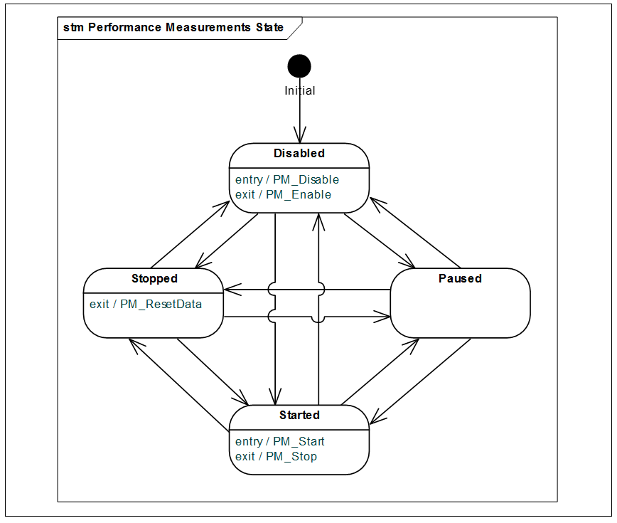
Figure 24. State of Performance Measurements State
PerfMeasurementsState Structure
Syntax
struct PerfMeasurementsState
{
    uint32_t  state;
};
Members
enabled
Indicates whether performance is measured,
0 – Disabled (this is the system default),
1 – Stopped,
2 – Started,
3 – Paused.
Global Performance Data
The management service requests the value of this Base FW property to retrieve performance data captured on the DSP. The firmware sends a list of items reported by firmware components. KCPS are sampled each DSP system tick (1ms in D0) for low latency and infrastructure components, or each processed frame otherwise. The KCPS are used to compute reported peak and average values by firmware.
Data items reported for resource_id = {module_id = 0, instance_id = <core_id>} contain the total KCPS spent on each active core.
This parameter reports only KCPS, while the memory state is reported by the Memory State Info parameter.
GlobalPerfData Structure
Syntax
struct GlobalPerfData
{
    uint32_t      perf_item_count;
    PerfDataItem  perf_items[];
};
Members
perf_item_count
Specifies number of items in perf_items array.
perf_items
Array of global performance measurements.
PerfDataItem Structure
Syntax
struct PerfDataItem
{
    uint32_t  resource_id;

    uint32_t  power_mode : 1;
    uint32_t  rsvd       : 30;
    uint32_t  is_removed : 1;

    uint32_t  peak_kcps;
    uint32_t  avg_kcps;
};
Members
resource_id
ID of the FW component.
{module_id = 0 | module_instance = core_id } reports total load measured on a core identified by core_id.
pewer_mode
0 – D0,
1 – D0i3.
is_removed
Indicates whether the component still exists (0) or has been already deleted (1).
peak_kcps
Peak KCPS captured.
avg_kcps
Average KCPS measured.
L2 Cache Info
The management service requests the value of this Base FW property to retrieve information about the current state of L2 Cache. It is available on platforms where the L2 cache is in use, otherwise ADSP_IPC_UNAVAILABLE is returned.
L2CacheInfo Structure
Syntax
struct L2CacheInfo
{
    uint32_t                 lock_status;
    uint32_t                 memory_descriptors_count;
    L2CacheMemoryDescriptor  memory_descriptor[];
};
Members
lock_status
Lock status code.
0 – current FW may be successfully locked into L2 cache
memory_descriptors_count
Specifies number of items in memory_descriptor array.
memory_descriptor
Descriptors of memory areas to be locked.
L2CacheMemoryDescriptor Structure
Syntax
const uint16_t MRT_TYPE_CODE    = 0;
const uint16_t MRT_TYPE_RO_DATA = 1;
const uint16_t MRT_TYPE_RW_DATA = 2;

const uint16_t MRT_LOCK_PREFERENCE_L1     = 0;
const uint16_t MRT_LOCK_PREFERENCE_L2     = 1;
const uint16_t MRT_LOCK_PREFERENCE_L2_OPT = 2;

struct MemoryRegionAttribute
{
    uint32_t  type            : 4;
    uint32_t  lock_preference : 4;
    uint32_t  rsvd            : 24;
};

struct L2CacheMemoryDescriptor
{
    uint32_t               va;
    uint32_t               size_bytes;
    MemoryRegionAttribute  attribute;
};
Members
va
Virtual base address of memory area.
size_bytes
Size of memory area in bytes.
attribute
Attributes of memory area.
System Time
The management service sets this property to pass down information about the current system time. The firmware uses it to translate event timestamps (for example, logs, or probe packets) to the system time (current host time) domain.
Note for management service implementation:
- The value of system time is expressed in US
- Time is in UTC
- Epoch is 1601-01-01T00:00:00Z
SystemTime Structure
Syntax
struct SystemTime
{
    uint32_t  val_l;
    uint32_t  val_u;
};
Members
val_l
Lower DWORD of current system time value.
val_u
Upper DWORD of current system time value.
Mix In
UUID: 39656EB2-3B71-4049-8D3F-F92CD5C43C09
Initial Configuration
Mix In accepts the basic module configuration, BaseModuleCfg, without extensions.
Audio Data Format
Table 60. Mix In Audio Data Format
| Interface | Sampling Rate | Number of Channels | Sample Size | Container Size |
|---|---|---|---|---|
| Input [0] | * | 1+ | 32-bit | 32-bit |
| Output [0] | Same as input | 1+ | 32-bit | 32-bit |
Frame Size
Mix In works on a 1ms frame.
Memory Requirements
Table 61. Mix In Memory Requirements
| Component | Size (bytes) | Remarks |
|---|---|---|
| Object | 168 | |
| Stream latency data | 56 | Only if MixIn’s parent pipeline is attached to a host output gateway. |
Runtime Parameters
Table 62. Mix In Runtime Parameters
| Parameter | ID | Dir | Type |
|---|---|---|---|
| UNDERRUN_NOTIF_PERIOD | 0 | R/W | Small |
| MIXER_MODE | 1 | W | Large |
Underrun Notification Period
The management service sends this configuration parameter to set the minimal notification period. The default value is set to 10ms.
Note The End-of-Stream variant of underrun notification does not honor the minimal notification period. It is always sent instantly.
Mixer Mode
This configuration parameter is sent to remap input channels into another channel slot, as defined per each individual connected Mix Out’s channel map. The Mix Out channel map may also define a different number of channels than Mix In’s input. Therefore, Mix In needs to know not only the target positions of its input channels, but also the output channel count, so that it can iterate to the next output sample group correctly.
MixerModeConfig Structure
Syntax
struct MixerModeConfig
{
    uint32_t             mixer_mode_config_count;
    MixerModeSinkConfig  mixer_mode_sink_configs[];
};
Members
mixer_mode_config_count
Number of items in mixer_mode_sink_configs.
mixer_mode_sink_configs
Array of channel map, one per each connected Mix Out’s sink.
MixerModeSinkConfig Structure
Syntax
struct MixerModeSinkConfig
{
    uint32_t  output_queue_id;
    uint32_t  mixer_mode;
    uint32_t  output_channel_count;
    uint32_t  output_channel_map;
};
Members
output_queue_id
Index of the output queue to be configured.
mixer_mode
Mode of channel remapping.
0 – Normal mode (the default identity mode),
1 – Channel remapping mode.
output_channel_count
Number of channels configured at Mix Out connected to this output queue. This item is valid only if mixer_mode is set to 1.
output_channel_map
Map of channels at Mix Out connected to this output queue.
This item is valid only if mixer_mode is set to 1. For detailed definition of channel map used for remapping, refer to the CopierModuleCfg structure documentation.
Mix Out
UUID: 3C56505A-24D7-418F-BDDC-C1F5A3AC2AE0
Initial Configuration
Mix Out accepts the basic module configuration, BaseModuleCfg, without extensions.
Audio Data Format
Table 63. MixOut Audio Data Format
| Interface | Sampling Rate | Number of Channels | Sample Size | Container Size |
|---|---|---|---|---|
| Input [n] | * | 1+ | 32-bit | 32-bit |
| Output [0] | Same as input | 1+ | 32-bit | 32-bit |
Frame Size
Mix Out works on a 1 ms frame.
Memory Requirements
Table 64. Mix Out Memory Requirements
| Component | Size (bytes) | Remarks |
|---|---|---|
| Object | 392 | |
| Common sink buffer | OBS | Equals to OBS parameter specified as a part of the module configuration. |
Runtime Parameters
None.
Copier
UUID: 9BA00C83-CA12-4A83-943C-1FA2E82F9DDA
Copier may be instantiated and bound in one of following configurations:
- Input DMA Gateway → Copier → another module instance …,
- … another module instance → Copier → Output DMA Gateway,
- … another module instance → Copier → another module instance …
In the first two configurations, the initial configuration must include Gateway Configuration data and the valid Node ID of the gateway to be connected on either Copier’s end.
The initial configuration data allows you to set up the audio format of the main Copier’s pins (input pin #0 and output pin #0), and to prepare a PCM conversion routine (if required). However, Copier supports two output pins. Before an extra output pin is used in a binding operation, the management service must first send the runtime parameter SET_SINK_FORMAT to set up a PCM conversion routine, if one is required.
Initial Configuration
Copier requires CopierModuleCfg, a basic module configuration with extensions.
Audio Data Format
Table 65. Copier Audio Data Format
| Interface | Sampling Rate | Number of Channels | Sample Size | Container Size |
|---|---|---|---|---|
| Input [0] | * | 1+ |
32-bit |
32-bit |
| Output [n] | Same as input | 1+ |
32-bit |
32-bit |
Frame Size
Copier works on a 1ms frame. The exact number of samples depends on the sampling rate.
Data Structures
CopierModuleCfg Structure
Syntax
struct CopierModuleCfg : BaseModuleCfg
{
    AudioDataFormatIpc out_fmt;
    uint32_t           copier_feature_mask;
    CopierGatewayCfg   gtw_cfg;
};
Members
out_fmt
Audio format of the output pin #0.
copier_feature_mask
Additionally defines copier behavior
- Bit [0] – Fast Mode:
1 – copies as many data as possible with regards to input/output queues state
0 – copying is limited to 1ms of data.
gtw_cfg
Gateway configuration [optional] specified by the management service if copier instance is to be connected to a DMA gateway on either end.
Remarks
When Copier is attached to an input gateway, the input channel_mask is ignored, while the output channel mask is used to remap channels coming from the input DMA to the channels of stream outputted by the Copier. Each half-byte of the channel map is an index of the input DMA stream channel that should be copied to the position determined by this half-byte index.
For example:
out_fmt.channel_map = 0xFFFFFF00 means that channel[0] from the input stream should be copied to the channel[0] of the output stream and also duplicated as a channel[1] of the output stream.
out_fmt.channel_map = 0xFFFFFF10 means exact copy of stereo stream,
out_fmt.channel_map = 0xFFFFFF01 means that stereo stream is copied with swapped channels.
When Copier is attached to an output gateway, the input channel_mask is interpreted as above, while out_fmt.channel_mask is ignored.
CopierGatewayCfg Structure
Configuration of a gateway that the instance of the Copier module is attached to.
The structure of the configuration data is presented in the following figure.
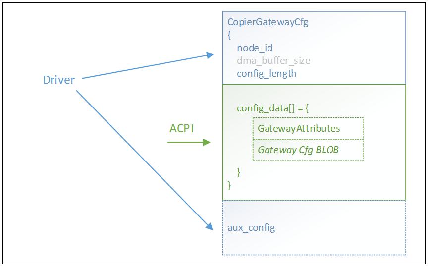
Figure 25. DMA Gateway Configuration Structure
The DMA Gateway configuration begins with CopierGatewayCfg, specified by the management service, where the node_id structure depends on the DMA type.
It is followed by the DMA-specific configuration that is copied from the ACPI tables and is transparent to the management service. config_length is set to the size of the configuration BLOB, and the content is appended to the CopierGatewayCfg. This part of the configuration BLOB may begin with the GatewayAttributes structure (optional), followed by an optional configuration BLOB that is specific for the DMA gateway type.
Another optional DMA-specific configuration (aux_config in the figure) may also be present. It is a structure that is known to the management service and is specified by the management service. For example, I2sDmaControlData or other i2s parameters are controlled directly by the management service in the case of an i2s DMA gateway.
For detailed documentation on DMA gateway configurations, see Section “Initial Gateway Configuration”.
Syntax
struct CopierGatewayCfg
{
    uint32_t node_id;
    uint32_t dma_buffer_size;
    uint32_t config_length;
    uint32_t config_data[];
};
Members
node_id
ID of the gateway connected to either input pin #0 or output pin #0, depending on the gateway’s direction. Set to INVALID_NODE_ID (-1) if no gateway is being connected. If no gateway is connected, the rest of the structure is ignored.
See also ConnectorNodeId structure.
dma_buffer_size
Preferred size of the gateway buffer (in bytes).
config_length
Size of the config_data (in DWORDS), may be 0 if the type of gateway used does not require configuration data.
config_data
Gateway configuration BLOB. See next sections for details. The actual size of the array is specified in the config_length field.
Remarks
FW attempts to allocate DMA buffer size according to dma_buffer_size value, however it may fall back to IBS (or OBS) * 2 size in case there is no memory available for deeper buffering.
ConnectorNodeId Structure
Base structure of a gateway address. Virtual index value is expected to be encoded in a gateway-specific way, depending on the actual type of gateway.
Syntax
struct ConnectorNodeId
{
    union
    {
        uint32_t dw;
        struct
        {
            uint32_t v_index    : 8;
            uint32_t dma_type   : 5;
            uint32_t _rsvd      : 19;
        } f;
    } val;
};
Members
dma_type
Type of the gateway. One of:
kDmicLinkInputClass = 11,
kI2sLinkOutputClass = 12,
kI2sLinkInputClass = 13,
kIPCOutputClass = 18,
kIPCInputClass = 19,
v_index
Index of the virtual DMA at the gateway.
Initial Gateway Configuration
Some gateway types require a configuration BLOB with additional settings, while others do not.
The gateway configuration BLOB may be preceded by the GatewayAttributes structure, which is defined here.
GatewayAttributes Structure
Syntax
struct GatewayAttributes
{
    uint32_t lp_buffer_alloc : 1;
    uint32_t _rsvd           : 31;
};
Members
lp_buffer_alloc
Indicates whether FW should attempt (if set to 1) to allocate the gateway buffer in Low-Power memory area.
i2s Gateway Configuration
The i2s configuration BLOB, coming from BIOS, may be followed by more control parameters that are specified by the management service as a TLV array. The array may contain the following items (both are optional):
- I2sDmaControlData structure
- M/N divider configuration
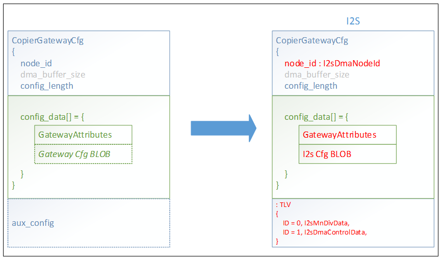
Figure 26. i2s Gateway Configuration Structure
I2sDmaNodeId Structure
i2s gateway address.
Syntax
struct I2sDmaNodeId : ConnectorNodeId
{
    union VirtualIndex
    {
        uint8_t b;
        struct
        {
            uint8_t time_slot_group_index   : 4;
            uint8_t i2s_instance            : 4;
        } f;
    };
};
Members
time_slot_group_index
Index of the time slot group within the i2s instance.
i2s_instance
Index of the i2s instance
Remarks
TDM time slots are assigned statically to streams by definition coming from ACPI. A single stream transmits data through time slots of a single time slot group.
For example, eight TDM time slots may be grouped by the following definition from ACPI:
tsd[0] = 0xFFFFFF43, tsd[1] = 0xFFFFFF01, …
Stream #0 specifies time_slot_group_index = 1, Stream #1 uses time_slot_group_index = 0 that would mean that 1st TDM slot is mapped to S0 Ch0, 0th TDM slot is mapped to S0 Ch1, 3rd TDM slot is mapped to S1 Ch0, and 4th TDM slot is mapped to S1 Ch1.
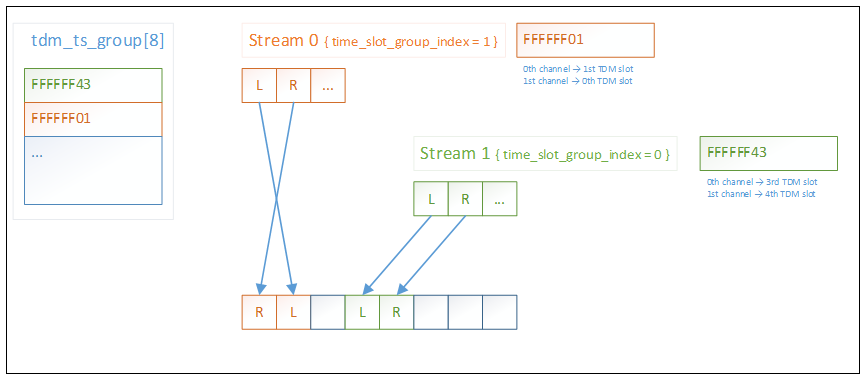
Figure 27. TDM Time Slots
i2s Gateway Configuration BLOB
Note For i2s Gateway BLOB details, contact your Intel representative.
The configuration BLOB that is passed to the Copier when attached to an i2s gateway consists of i2s register settings and a total of 8+12 DWORDs: eight per TDM time slot group mapping, 10 per i2s instance, and two for global MCLK configuration. The DWORDs are in the following order.
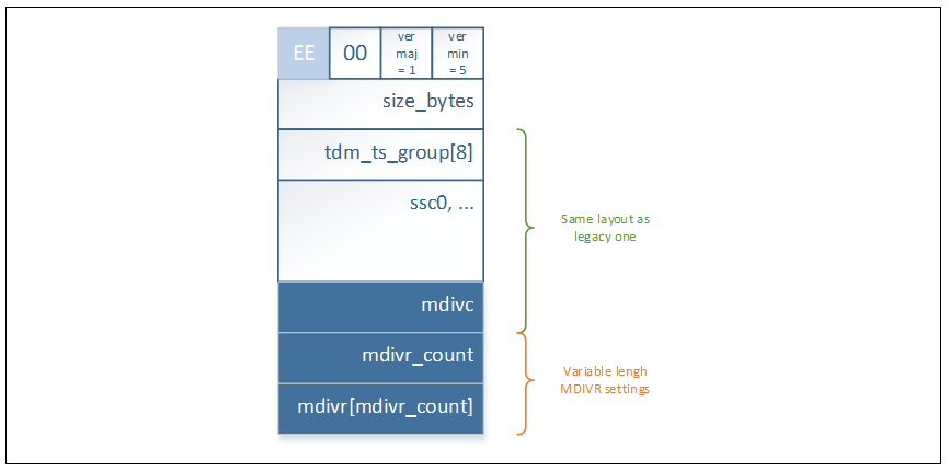
Figure 28. I2S Configuration
Syntax
BLOB
struct I2sConfigurationBlob_ver_1_5
{
   // header part
   uint32_t ver_min : 8; // set to 0x05
   uint32_t ver_maj : 8; // set to 0x01
   uint32_t rsvd0   : 8; // set to 0x00
   uint32_t sig     : 8; // set to 0xEE

   uint32_t size_bytes;

   uint32_t tdm_ts_group[8];
   uint32_t ssc0;
   uint32_t ssc1;
   uint32_t sscto;
   uint32_t sspsp;
   uint32_t sstsa;
   uint32_t ssrsa;
   uint32_t ssc2;
   uint32_t sspsp2;
   uint32_t ssc3;
   uint32_t ssioc;

   uint32_t mdivc;
   uint32_t mdivr_count;
   uint32_t mdivr[];
};
Members
tdm_ts_group
TDM time slot mappings.
There may be up to 8 groups (number of TDM slots) defined.
ssc0, ssc1, ssto, sspsp, sstsa, ssrsa, ssc2, sspsp2, ssc3, ssioc
i2s HW registers. Refer to the i2s HW specification for details.
mdivc
MDIVC – Master Clock Divider Control Register.
mdivr_count
Number of items in mdivr array.
mdivr
Array of MDIVxR – Master Clock Divider x Ratio Register
Remarks
The master clock is common for all i2s interfaces. Therefore, all i2s instances should be configured using the same MCLK settings. If MCLK is already running, FW checks the MCLK configuration against the operating configuration. The setting is applied once any i2s gateway exists. If no i2s instance is used, the MCLK is disabled.
Additional i2s Control Parameters
I2sMnDivData Structure
I2sMnDivData structure may be a part of TLV-encoded array that follows DmaControl or CopierGatewayCfg structure in the DMA Control configuration parameter payload when node_id specifies an i2s gateway.
The ID of the TLV is set to 0.
Syntax
struct Is2MnDivData
{
    uint32_t m_div_val;
    uint32_t n_div_val;
};
Members
m_div_val
Value of M.
n_div_val
Value of N.
I2sDmaControlData Structure
I2sDmaControlData structure may be a part of TLV-encoded array similarly to I2sMnDivData.
The ID of the TLV is set to 1.
Syntax
struct I2sDmaControlData
{
    uint32_t clock_warm_up    : 16;
    uint32_t mclk             : 1;
    uint32_t warm_up_ovr      : 1;
    uint32_t rsvd0            : 14;

    uint32_t clock_stop_delay : 16;
    uint32_t keep_running     : 1;
    uint32_t clock_stop_ovr   : 1;
    uint32_t rsvd1            : 14;
};
Members
clock_warm_up
Delay in msec between enabling interface (moment when Copier instance is being attached to the interface) and actual interface start. Value of 0 means no delay.
mclk
Specifies if parameters target MCLK (1) or SCLK (0).
warm_up_ovr
Value of 1 means that clock should be started immediately even if no Copier instance is currently attached to the interface.
clock_stop_delay
Delay in msec between stopping the interface (moment when Copier instance is being detached from the interface) and interface clock stop. Value of 0 means no delay.
keep_running
Value of 1 means that clock should be kept running (infinite stop delay) after Copier instance detaches from the interface.
clock_stop_ovr
Value of 1 means that clock should be stopped immediately.
DMIC Gateway Configuration
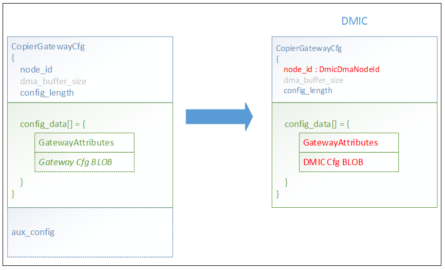
Figure 29. DMIC Gateway Configuration
DmicDmaNodeId Structure
DMIC gateway address.
Syntax
struct DmicDmaNodeId : ConnectorNodeId
{
    union VirtualIndex
    {
        uint8_t b;
        struct
        {
            uint8_t dmic_interface_queue_id :3;
            uint8_t time_slot_group_index   :2;
            uint8_t instance                :3;
        } f;
    };
};
Members
dmic_interface_queue_id
Index of the input queue within the DMIC instance specified by instance.
time_slot_group_index
Index of the time slot group within the queue specified by the queue ID.
instance
Index of DMIC instance.
Remarks
See the I2sDmaNodeId structure documentation for more details about time slot group indexing.
DMIC Gateway Configuration BLOB
Note For DMIC Gateway BLOB details, contact your Intel representative.
The configuration BLOB that is passed to the Copier when attached to a DMIC gateway has the following structure.
DmicConfigurationBlob Structure
Syntax
struct DmicConfigurationBlob
{
    uint32_t    ts_group[4];
    GlobalCfg   global_cfg;
    uint32_t    channel_ctrl_mask;
    ChannelCfg  channel_cfg[];
    uint32_t    pdm_ctrl_mask;
    PdmCtrlCfg  pdm_ctrl_cfg[];
};
Members
ts_group
Time slot mappings.
global_cfg
Global configuration settings (see below).
channel_ctrl_mask
Specifies PDM channels to be programmed using data from channel_cfg array.
bit [0] = 1 means that configuration for PDM channel 0 is provided.
bit [1] = 1 means that configuration for PDM channel 1 is provided.
channel_cfg
PDM channel configuration settings (see below).
pdm_ctrl_mask
Specifies PDM controllers to be programmed using data from pdm_ctrl_cfg array.
bit [0] = 1 means that configuration for PDM controller 0 is provided.
bit [1] = 1 means that configuration for PDM controller 1 is provided.
pdm_ctrl_cfg
PDM controller configuration settings (see below).
GlobalCfg Structure
Syntax
struct GlobalCfg
{
    uint32_t clock_on_delay;
};
Members
clock_on_delay
Specifies delay in ms to unmute mics after clock is started.
Expected value is 1-3ms.
Typical value is 1ms.
ChannelCfg Structure
Syntax
struct ChannelCfg
{
    uint32_t out_control;
};
Members
out_control
OUTCONTROL
PdmCtrlCfg Structure
Syntax
struct PdmCtrlCfg
{
    uint32_t  cic_control;
    uint32_t  cic_config;
    uint32_t  rsvd0;
    uint32_t  mic_control;
    uint32_t  pdmsm;
    uint32_t  rsvd1[3];
    FirCfg    fir_config[2];
    uint32_t  fir_coeffs[n];
};
Members
cic_control
CIC_CONTROL
cic_config
CIC_CONFIG
rsvd0
Reserved field
mic_control
MIC_CONTROL
pdmsm
PDM SoundWire Map. This field is used on platforms with SoundWire, otherwise it is ignored.
rsvd1
Reserved field
fir_config
FIR configurations
fir_coeffs
Array of FIR coefficients, channel A first, then channel B.
n – Actual size of the array depends on the number of active taps of the FIR filter for channel A plus the number of active taps of the FIR filter for channel B (see FIR_CONFIG) and on the unpacked/packed form of values (see Remarks).
Remarks
Size of a single coefficient is 20-bit. Coefficients may be sent in either unpacked form where each value takes one DWORD (32-bits) or in packed form where the array begins with a single DWORD of 0xFFFFFFFF value to indicate packed form (unpacked coefficient has always most significant byte set to 0) followed by array of 24-bit values (in little endian form).
FirCfg Structure
Syntax
struct FirCfg
{
    uint32_t fir_control;
    uint32_t fir_config;
    uint32_t dc_offset_left;
    uint32_t dc_offset_right;
    uint32_t out_gain_left;
    uint32_t out_gain_right;
    uint32_t rsvd[2];
};
Members
fir_control
FIR_CONTROL
fir_config
FIR_CONFIG
dc_offset_left
DC_OFFSET_LEFT
dc_offset_right
DC_OFFSET_RIGHT
out_gain_left
OUT_GAIN_LEFT
out_gain_right
OUT_GAIN_RIGHT
rsvd
Reserved field
Note: If only one PDM controller configuration is passed, the other (missing) one is configured by the management service by clearing CIC_CONTROL.SOFT_RESET bit.
Note: The management service must ensure that all mics are disabled before starting to program PDM controllers.
Additional DMIC Control Parameters
DmicClockControlData Structure
DmicClockControlData structure may be a part of TLV-encoded array sent by the management service as a DMA Control configuration request.
The ID of the TLV is set to 0.
Syntax
struct DmicClockControlData
{
    uint32_t pdm_ctrl_mask    : 32;

    uint32_t pdm_0_en_a       : 1;
    uint32_t pdm_0_en_b       : 1;
    uint32_t pdm_1_en_a       : 1;
    uint32_t pdm_1_en_b       : 1;

    uint32_t rsvd0            : 28;
};
Members
pdm_ctrl_mask
Specifies which pdm_<x>_en_a/b pairs are valid.
pdm_<x>_en_a/b
Specifies whether a/b clock of PDM <x> should be enabled.
Remarks
Each PDM that is addressed by pdm_ctrl_mask must be programmed by configuration BLOB previously provided by a Copier instance otherwise request is rejected.
IPC Gateway Configuration
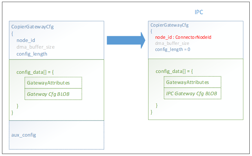
Figure 30. IPC Gateway Configuration Structure
IPC Gateway Configuration BLOB
The configuration BLOB passed to the Copier when being attached to an IPC gateway.
Syntax
struct IpcGtwCfg
{
    uint32_t buffer_size;
    union
    {
        struct
        {
            uint32_t notif_high : 1;
            uint32_t notif_low : 1;
            uint32_t rsvd : 30;
        };
        uint32_t flags_raw;
    };
    uint32_t threshold_high;
    uint32_t threshold_low;
};
Members
buffer_size
Size of internal buffer maintained by an IPC gateway.
notify_high
Flag specifies if GATEWAY_HIGH_THRES IPC notification should be sent when threshold_high is reached.
notify_low
Flag specifies if GATEWAY_LOW_THRES IPC notification should be sent when threshold_low is reached.
threshold_high
Specifies amount of data in internal gateway buffer when GATEWAY_HIGH_THRES IPC is sent if notify_high is enabled.
threshold_low
Specifies amount of data in internal gateway buffer when GATEWAY_LOW_THRES IPC is sent if notify_low is enabled.
Memory Requirements
Table 66. Copier Memory Requirements
| Component | Size (bytes) | Remarks |
|---|---|---|
| Object | 224 | |
| Copy of configuration | size of CopierModuleCfg |
Actual size of the configuration, including actual size of config_data. Only if copier is connected to a gateway. |
| Copy of gateway state |
HD/A Link Output: 20 HD/A Host Output: 24 + 4 * number of 4KB pages required for DMA buffer (if not LL buffer) |
Only if copier is connected to a gateway and pipelines may be saved to host memory. |
| Virtual Channels Slot Map | 12 | Only if copier is connected to a gateway. |
Runtime Parameters
Table 67. Copier Runtime Parameters
| Parameter | ID | Dir | Type |
|---|---|---|---|
| TIMESTAMP_INIT | 1 | W | Large |
| SET_SINK_FORMAT | 2 | W | Large |
| DATA_SEGMENT_ENABLED | 3 | R/W | Large |
| LLP_READING | 4 | R | Large |
| GET_DATA | 5 | R | Large |
| SET_DATA | 6 | W | Large |
Timestamp Init
The management service sends this configuration parameter to trigger time stamping flow.
Once the timestamp is captured, Copier sends back a Timestamp Captured Notification.
| Type | Length (Bytes) | Value |
|---|---|---|
|
TIMESTAMP_INIT tsctrl_reg – Contains low-level configuration for timestamp init, passed through directly into <ifc>_LOCAL_TS_Contol register of corresponding HW i/f within DSP Timestamping registers. |
4 |
struct TimestampInitData { |
Set Sink Format
The management service sends this configuration parameter to configure the audio format of the Copier’s output pin that is to be bound to another module instance. The management service resends the audio format of the input pin, as Copier might have been unbound from previous source and is to be bound to a new source. If Copier is still bound to a source, the audio format of the input pin must be the same as the current source.
Table 69. Set Sink Format
| Type | Length (Bytes) | Value |
|---|---|---|
|
SET_SINK_FORMAT sink_id – Index of the output pin. src_fmt – Audio format of the input pin. sink_fmt – Audio format of the specified output pin. |
52 |
struct SetSinkFormat { |
Data Segment Enabled
The management service sends this configuration parameter to an instance of a Copier that is attached to a Gateway, to enable or disable the sending of a Stream Data Segment Notification to the host.
The Node ID may be unspecified (set to INVALID_NODE_ID (-1)) if the Copier is attached to a single Gateway (which is currently the case, as Copier does not support gateway-to-gateway mode).
The notification is sent every segment that is transferred until it is canceled by the management service.
Table 70. Data Segment Enabled
| Type | Length (Bytes) | Value |
|---|---|---|
|
DATA_SEGMENT_ENABLED node_id – Gateway node ID. enabled – indicates whether notification should be enabled (1) or disabled (0). data_seg_size – data segment size (in bytes). |
12 |
struct DataSegmentEnabled { |
LLP (Linear Link Position) Reading
The management service requests this property from a Copier associated with a DMA Gateway that does not support direct LLP reading from host CPU. In this situation, the DSP firmware must read LLP from hardware registers.
The current LLP value and the current Wallclock value are provided, to allow the management service to adjust the LLP with IPC response delay.
Table 71. LLP Reading
| Type | Length (Bytes) | Value |
|---|---|---|
|
LLP_READING llpl_l – lower part of 64-bit LLP llpl_u – upper part of 64-bit LLLP local_tsc_l – lower part of 64-bit Wallclock local_tsc_u – upper part of 64-bit Wallclock |
16 |
struct LlpReading { |
Gateway Notification Period
See MixIn Underrun Notification Period.
Get Data
The management service sends this configuration parameter to obtain data from the IPC gateway connected with Copier.
Set Data
The management service sends this configuration parameter to upload data to the IPC gateway connected with Copier.
Peak Volume Control
UUID: 8A171323-94A3-4E1D-AFE9-FE5DBAA4C393
Initial Configuration
Peak Volume requires PeakVolumeModuleCfg, a basic module configuration with some extensions.
Audio Data Format
Table 72. PeakVol Audio Data Format
| Interface | Sampling Rate | Number of Channels | Sample Size | Container Size |
|---|---|---|---|---|
| Input [0] | 1 | 1..8 |
32-bit 16-bit* |
32-bit 16-bit* |
| Output [0] | Same as input | 1+ | Same as input | Same as input |
Note
- No volume control works in 16 bit / 16-bit mode, only peak metering is supported
Frame Size
PeakVol works on 1ms frame.
Data Structures
PeakVolumeModuleCfg Structure
Syntax
struct PeakVolumeModuleCfg : BaseModuleCfg
{
    PeakVolumeConfig config[1];
};
Members
config
Configuration, one item per input channel.
PeakVolumeConfig Structure
Syntax
struct PeakVolumeConfig
{
    uint32_t channel_id;
    uint32_t target_volume;
    uint32_t curve_type;
    uint64_t curve_duration;
};
Members
channel_id
Index of the input channel. ALL_CHANNELS (0xFFFFFFFF) value indicates all channels to be addressed.
target_volume
Target volume. Should be converted by the management service to linear value as target_volume=0x7FFFFFFF*10^(dbVal/1310720).
Note: -2147483648 (0x80000000 in hexadecimal, or LONG_MIN) is -Infinity decibels (attenuation) – should be specified as 0.
curve_type
One of NONE = 0, WINDOWS_FADE = 1.
curve_duration
Duration of curve expressed in hundreds of nanoseconds.
Memory Requirements
Table 73. Peak Volume Memory Requirements
| Component | Size (bytes) | Remarks |
|---|---|---|
| Object | 416 |
Runtime Parameters
Table 74. Peak Volume Runtime Parameters
| Parameter | ID | Dir | Type |
|---|---|---|---|
| VOLUME | 0 | R/W | Large |
Volume
When the volume parameter is set by the management service, a single PeakVolumeConfig instance is expected to be in the parameter data. The channel ID may indicate either a single target channel (0..n-1) or all channels (ALL_CHANNELS).
When the volume parameter is retrieved by the management service, the parameter data contains multiple PeakVolumeConfig instances (one per channel).
Gain
UUID: 61BCA9A8-18D0-4A18-8E7B-2639219804B7
Gain module interface is identical to the one provided by Peak Volume Control. The difference is that Gain does not report peak values in the FW Registers area.
Up Down Mixer
UUID: 42F8060C-832F-4DBF-B247-51E961997B34
Initial Configuration
Up Down Mixer requires UpDownMixerCfg, a basic module configuration with some extensions.
Audio Data Format
| Interface | Sampling Rate | Number of Channels | Sample Size | Container Size |
|---|---|---|---|---|
| Input [0] | * |
1 |
32-bit | 32-bit |
| Output [0] | Same as input |
2 |
32-bit | 32-bit |
Frame Size
Up Down Mixer works on a 1ms frame.
Data Structures
UpDownMixerCfg Structure
Syntax
struct UpDownMixerCfg : BaseModuleCfg
{
    ChannelConfig        out_channel_config;
    UpDownMixCoeffSelect coefficients_select;
    int32_t              coefficients[1];
};
Members
out_channel_config
Configuration of the output channels (instead of full output format specification as other properties stay the same).
coefficients_select
Indicates whether the module uses built-in coefficients and default channel map or the ones sent within this structure.
0 - Indicates whether module uses default built-in coefficients (when set to 0), or the ones specified in this structure (when set to 1).
coefficients
Array of coefficients values. When coefficients are specified (coefficients_select = 1), the actual length of this array is 6. Otherwise it is 0.
Memory Requirements
Table 76. Up Down Mixer Memory Requirements
| Component | Size (bytes) | Remarks |
|---|---|---|
| Object | 144 | |
| Coefficients | 32 | When custom coefficients are specified by the management service. |
Runtime Parameters
None.
SRC
UUID: e61bb28d-149a-4c1f-b709-46823ef5f5ae
Initial Configuration
SRC requires SrcIntcCfg, a basic module configuration with some extensions.
Audio Data Format
Table 77. SRC Audio Data Format
| Interface | Sampling Rate [kHz] | Number of Channels | Sample Size | Container Size |
|---|---|---|---|---|
| Input [0] |
8 |
1..8 | 32-bit | 32-bit |
| Output [0] |
8 |
Same as input | 32-bit | 32-bit |
Frame Size
SRC frame size may be as small as 1ms.
Data Structures
SrcIntcCfg Structure
Syntax
struct SrcIntcCfg : BaseModuleCfg
{
    SamplingFrequency out_freq;
};
Members
out_freq
Output frequency.
Memory Requirements
Table 78. SRC Memory Requirements
| Component | Size (bytes) | Remarks |
|---|---|---|
| Object | 16816 | -4096 if stack is allocated from pipeline memory pool. |
Runtime Parameters
None.
Mic Selection/LL-DMIX
UUID: 32FE92C1-1E17-4FC2-9758-C7F3542E980A
Both modes of work are supported by a single logic provided by the ITP PP team. The API supports input-to-output channel map. If more than a single input channel is mapped to the same output channel, the average value of the inputs is computed as the output value.
The following settings are used to configure mode of work:
- Mic Selection
- Either multiple input channels are mapped to the output channel #0 so the average value from all specified mics is computed as output,
- Or single (dynamically selected) mic channel is mapped to the output channel #0 and input from that channel is copied to the output channel.
- LL-DMIX
- In this mode, the map is statically defined by the adapter (shim) as average from input channel #0 and input channel #1 to output channel #0.
Audio Data Format
Table 79. Mic Selection Audio Data Format
| Interface | Sampling Rate | Number of Channels | Sample Size | Container Size |
|---|---|---|---|---|
| Input [0] | 16 kHz | 1..8 | 16 bit | 16 bit |
| Output [0] | 16 kHz | 1..8 | 16 bit | 16 bit |
Frame Size
Input and output frame size is 1ms (16 samples) as the module works in LL domain.
Memory Requirements
Table 80. Mic Selection/LL-DMIX Memory Requirements
| Component | Size (bytes) |
|---|---|
| Object | 960 |
Probe
UUID: 20A1F350-19B4-428A-BEF6-F7C27CB8B5FB
Probe is a loadable module.
Since Probe is designed as a standalone module (no parent pipeline assigned), its instance must be deleted explicitly by sending the Delete Instance IPC request.
Initial Configuration
Probe requires ProbeModuleConfig, a basic module configuration with some extensions.
The Probe module is a standalone block, and does not belong to any pipeline. Therefore, ppl_instance_id should be set to INVALID_PIPELINE_ID (-1) in the Init Instance IPC request. If the management service provides the ID of any existing pipeline, it is ignored by the firmware.
Probe is not invoked in any audio data processing chain. Therefore, both the audio data format and the input/output frame sizes specified in the initial configuration are unused.
There is no dedicated execution context, therefore core_id should be set to 0.
Init Instance IPC request = {
	instance_id = 0, 	       // single instance
	proc_domain = 0, 	       // ignored by FW
	core_id = 0, 		       // ignored by FW,
	ppl_instance_id = INVALID_PIPELINE_ID, // no parent
                                              // pipeline
}
ProbeModuleCfg Structure
Syntax
struct ProbeModuleCfg : BaseModuleCfg
{
    ProbeGatewayCfg  gtw_cfg;
};
Members
gtw_cfg
Configuration of the probe capture (host input) gateway.
ProbeGatewayCfg Strtucture
Syntax
struct ProbeGatewayCfg
{
    uint32_t node_id;
    uint32_t dma_buffer_size;
};
Members
node_id
ID of gateway used to transport extracted data to the host. This must be one of IPC host input gateway IDs. Should be set to INVALID_NODE_ID if no gateway is allocated (extraction will not be supported).
dma_buffer_size
Preferred size of the gateway buffer (in bytes).
Memory Requirements
Table 81. Probe Memory Requirements
| Component | Size (bytes) |
|---|---|
| Total BSS |
Runtime Parameters
Runtime parameters controls capture and insertion probes. Probes may be connected to a module instance’s input/output queue (supported for any module by the infrastructure). Probes may also be connected to an internal probe point inside the module instance, if supported by the target module instance implementation.
Probe point addressing is documented in the Probe Points parameter section.
Table 82. Probe Runtime Parameters
| Parameter | ID | Dir | Type |
|---|---|---|---|
| INJECTION_PROBE_DMA | 1 | R/W | Large |
| INJECTION_PROBE_DMA_DETACH | 2 | R/W | Large |
| PROBE_POINTS | 3 | R/W | Large |
| DISCONNECT_PROBE_POINTS | 4 | R/W | Large |
Injection Probe DMA
The management service writes this parameter to associate host output DMAs as injection probes with Probe module.
The management service may read this parameter to obtain the list of host output DMAs currently associated with Probe module.
ProbeDmaList Structure
Syntax
struct ProbeDmaList
{
    ProbeDma probe_dma[];
};
Members
probe_dma
Array of DMAs to be associated with the Probe module. Actual size of the list is specified by the data_off_size field in the message header.
ProbeDma Structure
Syntax
struct ProbeDma
{
    uint32_t  node_id;
    uint32_t  dma_buffer_size;
};
Members
node_id
ID of gateway. This must be one of IPC host gateway IDs (host output in case of an injection probe).
dma_buffer_size
Preferred size of the gateway buffer (in bytes).
Remarks
Attempt to assign a DMA that is already in use by Probe module or any other module results in error.
Injection Probe DMA Detach
The management service sends this configuration parameter to detach one or more probe DMAs from the Probe module.
ProbeDmaDetachList Structure
Syntax
struct ProbeDmaDetachList
{
    uint32_t node_id[];
};
Members
node_id
Array of gateway IDs to be detached. Actual size of node_id array is determined by size of the payload specified in the message header.
Remarks
Attempt to detach a DMA being in-use by any probe points results in error.
Attempt to detach a DMA that is not associated with Probe module completes successfully.
Probe Points
The management service writes this parameter to create probe points.
The management service may read this parameter to obtain the list of currently created probe points.
ProbePoints Structure
Syntax
struct ProbePoints
{
    ProbePointDesc probe_points[];
};
Members
probe_points
Array of probe point descriptors. Actual size is specified in the message header.
Remarks
All probes that are created by a single request are synchronously started at the same system tick by the FW.
Attempt to create/re-configure a probe point that already exists results in error.
Attempt to create a probe point associated with either unassigned or occupied DMA results in error.
Attempt to create a probe point targeted at non-exiting module instance results in error.
A probe point is automatically deleted while its target is being deleted.
ProbePointDesc Structure
Syntax
struct ProbePointDesc
{
    ProbePointId id;
    uint32_t     purpose;
    uint32_t     node_id;
};
Members
id
Probe point identifier. See ProbePointId.
purpose
Indicates connection purpose.
0 – Extract,
1 – Inject,
2 – InjectReextract.
node_id
Specifies injection gateway ID in case purpose is set to Inject or InjectReextract, otherwise set to INVALID_NODE_ID.
ProbePointId Structure
Syntax
struct ProbePointId
{
    uint32_t module_id   : 16;
    uint32_t instance_id : 8;
    uint32_t type        : 2;
    uint32_t index       : 6;
};
Members
module_id
Target module ID.
instance_id
Target module instance ID.
type
Type.
0 – Input,
1 – Output,
2 – Internal.
index
Specifies a 0-based index of the target module instance’s queue.
Disconnect Probe Points
The management service sends this configuration parameter to disconnect one or more probe points.
ProbePointList Structure
Syntax
struct ProbePointList
{
    ProbePointId probe_point_id[];
};
Members
probe_point_id
Array of probe point IDs to be disconnected. Actual size of the array is determined by size of the payload specified in the message header.
Remarks
Attempt to disconnect a non-exiting probe point is ignored by FW and does not raise an error.
Probe Data Stream
Extraction Data Format
Since a single extraction probe DMA is used to transfer data from multiple probe points, the data is packetized where the management service may expect that packets coming from different probe points are interleaved. Each pocket begins with the following header.
ProbeDataPacket Structure
Syntax
struct ProbeDataPacket
{
    uint32_t     sync_word;
    ProbePointId probe_point_id;
    ProbeDataFmt format;
    uint32_t     timestamp_low;
    uint32_t     timestamp_high;
    uint32_t     data_size_bytes;
    uint32_t     data[];
    uint64_t     checksum;
};
Members
sync_word
Set to 0xBABEBEBA.
probe_point_id
Probe point ID. See ProbePointId for details.
format
Data format. See ProbeDataFmt for details. Note that it may be either ProbeDataFmtBasic, or ProbeDataFmtStandard.
timestamp_low
Low DWORD of 64-bit timestamp read from wall clock.
timestamp_high
High DWORD of 64-bit timestamp read from wall clock.
data_size_bytes
Actual size of data[] array, expressed in bytes.
data
Data, padded to the DWORD boundary with zeroes.
checksum
Checksum (little-endian encoded), data[] not included.
Injection Data Format
The data being injected is a pure data stream, without any headers. It must be formatted accordingly to the format of the input/output pin or internal queue of the target module instance.
ProbeDataFmtBasic Structure
Syntax
struct ProbeDataFmtBasic
{
    uint32_t fmt_type       : 1; // = 0
    uint32_t basic_type_enc : 31;
};
Members
fmt_type
Format type, set to 0 to indicate Basic format.
basic_type_enc
Basic type encoding TBD.
ProbeDataFmtStandard Structure
Syntax
struct ProbeDataFmtStandard
{
    uint32_t fmt_type        : 1; // = 1
    uint32_t standard_type   : 4;
    uint32_t audio_fmt       : 4;
    uint32_t sample_rate     : 4;
    uint32_t nb_channels     : 5;
    uint32_t sample_size     : 2;
    uint32_t container_size  : 2;
    uint32_t sample_fmt      : 1;
    uint32_t sample_end      : 1;
    uint32_t interleaving_st : 1;
    uint32_T _rsvd_0         : 7;
};
Members
fmt_type
Format type, set to 1 to indicate Standard format.
standard_type
Stream type.
0 – Audio stream,
1 – Video stream.
audio_fmt
Audio encoding type.
0 – PCM,
1 – MP3,
sample_rate
Sample rate.
0 – 8 kHz,
1 – 11.025 kHz,
2 – 12 kHz,
3 – 16 kHz,
4 – 22.05 kHz,
5 – 24 kHz,
6 – 32 kHz,
7 – 44.1 kHz,
8 – 48 kHz,
9 – 64 kHz,
10 – 88.2 kHz,
11 – 96 kHz,
12 – 128 kHz,
13 – 176.4 kHz,
14 – 192 kHz,
15 – INVALID_SAMPLE_RATE.
nb_channels
Channel count. Zero based (0 means 1 channel, 1 means 2 channels and so on).
sample_size
Sample size in bytes. Zero based (0 means 1 byte, and so on).
container_size
Container size in bytes. Zero based.
sample_fmt
Sample format.
0 – integer format,
1 – 32-bit floating point format. Note that sample_size and container_size must be both set to 3 in this case.
sample_end
Sample endianness.
0 – Little endian,
1 – Big endian.
interleaving_st
Interleaving style.
0 – Sample interleaving,1 – Channel interleaving.
Management Service
Management Service is a standalone module (no parent pipeline assigned). It instantiates automatically after the firmware boots successfully. This section provides an example implementation of the management service in firmware. For example, the module allows you to configure hardware codecs, create a full audio pipeline, and start it with one IPC message.
The Module ID can be retrieved from firmware using the Module Info Base FW Parameter.
Pipeline
As part of the management service example, the audio pipeline shown in the following figure is implemented.
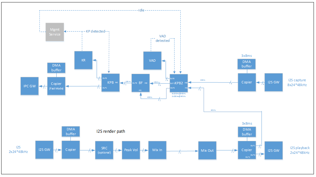
Figure 31. Audio Pipeline in Management Service
The capture part (the top part of diagram) of pipeline is created automatically and started. The device listens for a key phrase (KP). It notifies the host about KP detection with an IPC message, and starts streaming audio frames to the host via IPC gateway when the phrase is detected. The audio stream to the host can be stopped with the CLOUD_STOP IPC message.
The example implementation of the management service expects that the playback (render) pipeline is paused at the beginning. It activates once the host wants to deliver a response from Cloud via i2s.
Runtime Parameters
Table 83. Management Service Runtime Parameters
| Parameter | ID | Dir | Type |
|---|---|---|---|
| STOP_PLAYBACK | 1 | R/W | Large |
| START_PLAYBACK | 2 | R/W | Large |
| CLOUD_STOP | 3 | R/W | Large |
| PIPELINE_SOFT_RESET | 4 | R/W | Large |
Stop Playback
The host sends this configuration parameter to stop the playback pipeline.
Stop Playback
The host sends this configuration parameter to start the playback pipeline when, for example, a cloud response must be delivered.
Cloud Stop
The device starts streaming audio frames when a Key Phrase is detected. The host must send a Cloud Stop message to move to the “listening for KP” state.
Pipeline Soft Reset
The host sends this configuration parameter to delete, then recreate, the pipeline.
Modules Available in the Firmware
Module Categories
Modules are classified by processing domain (Low Latency versus Data Processing) and by packaging (Built-In versus Loadable).
Low Latency (LL) Modules
Properties of low latency (LL) modules:
- Processing is done in LL domain.
- Processes only LL 8ms chunks of data.
- Modules are executed in order of their parent pipeline priorities.
- Processing is done till completion (without preemption).
- Module is executed only on Core 0.
Data Processing (DP) Modules
Properties of DP modules:
- Processing in done in the DP domain.
- The size of the input frame is specified by a module.
- They are scheduled by EDF scheduler.
- Module is executed in dedicated task (one per module instance).
- Module is executed on a core assigned by the management service.
Built-In Versus Loadable Modules
Some modules are built-in modules, always present in firmware memory space and ready to be instantiated. Other modules are loadable modules that may be dynamically loaded and unloaded during runtime.
The Module Manager is initialized with a module list from the FM Image Manifest.
- The existence of built-in modules is guaranteed.
- To use loadable modules, the correct data must be loaded (.text and .rodata sections).
- Built-in modules are allocated on pipeline memory.
- Loadable modules have dedicated memory for module.
Firmware LL Modules
Copier Module (PCM converter)
This module serves as a 1:n simple bridge between pipelines. Copying data between the queues during LL cycles guarantees real-time data flow.
Copier consumes data from the attached input queue, 1ms of data at the time. The data is written to one or more output queues. Having multiple output queues resolves many problems with timing and size dependencies between outputs.
Copier also provides PCM conversion routines, and the ability to (de-)interleave samples while copying data to/from DMA Gateways. Providing this additional processing capability inside the Copier allows for a reduced number of memcpy operations and a reduced number of module instances created in the pipeline (PcmConverter is not needed).
Copier provides the following:
- Gateway (one per instance) handling
- PCM conversions
For more information, see Section “Copier”.

Figure 32. Copier Module
Mixer Modules (MixIn, MixOut)
The output of a MixIn module instance is always attached to a MixOut module instance by the Bind command. The output writes data from the input source to the MixOut’s sink interface. The data is written to the sink using a saturating ADD operation.
A MixIn instance uses a sink that maintains its private write pointer and global read pointer to determine the part of the buffer that can be written. However, it does not know whether its add operation is the first one at the current write position. Therefore, MixIn assumes that the part of the buffer that is not written by anyone yet is zeroed.
The MixOut module instance is the second part of the Mixer complex.
Since the state of the mixer buffer is recalculated by the sinks when MixIn instances write their data, the data processing routine just copies the common part to the target queue. Then, it iterates over the write pointers associated with the internal buffer and resets them to reflect recent data consumption.
The part of internal buffer that is consumed by the MixOut::ProcessData() function must be zeroed before ProcessData() exits, to ‘restart’ the next mixing (adding) operation at this place from 0.
MixOut supports up to eight ‘input’ sinks.
To satisfy pipeline latency computation requirements, MixOut must implement an artificial Source interface on top of the mixer buffer and register it in the source array. There is a single instance of Source (that reflects the already-mixed data coming into the MixOut) registered, not eight ones.
- Mixes all data from all connected MixIns
- Always has data ready on output
- Provides eight Sinks (virtualized over the same physical buffer)
- Has only one buffer per instance
For IPC Configuration, see Section “Mix In”, and Section “Mix Out”.
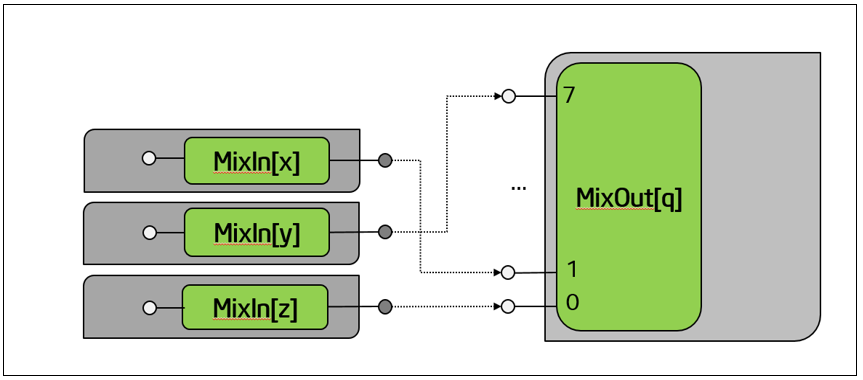
Figure 33. Mixer Modules
Peak Meter/Volume
The Peak Meter/Volume module provides the following:
- Input signal meter (per channel)
- Volume changing (per channel)
- Fade apply (optional per demand)
- Exposing set/measured parameters via memory window
For IPC Configuration, see Section “Get Data”.
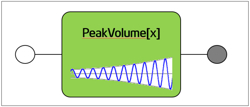
Figure 34. Peak Meter/Volume Module
UpDown Mixer
UpDown Mixer provides channel up- and down-mixing routines.
It supports the transformations shown in the following table.
Table 84. UpDownMixer Transformations
| Input Channel Configuration | Output Channel Configuration |
|---|---|
| CHANNEL_CONFIG_STEREO | CHANNEL_CONFIG_MONO |
| CHANNEL_CONFIG_MONO | CHANNEL_CONFIG_STEREO |
| CHANNEL_CONFIG_DUAL_MONO | CHANNEL_CONFIG_STEREO |
| CHANNEL_CONFIG_STEREO | CHANNEL_CONFIG_STEREO |
| CHANNEL_CONFIG_2_POINT_1 | CHANNEL_CONFIG_STEREO |
| CHANNEL_CONFIG_3_POINT_0 | CHANNEL_CONFIG_STEREO |
| CHANNEL_CONFIG_3_POINT_1 | CHANNEL_CONFIG_STEREO |
| CHANNEL_CONFIG_QUATRO | CHANNEL_CONFIG_STEREO |
| CHANNEL_CONFIG_4_POINT_0 | CHANNEL_CONFIG_STEREO |
| CHANNEL_CONFIG_5_POINT_0 | CHANNEL_CONFIG_STEREO |
| CHANNEL_CONFIG_5_POINT_1 | CHANNEL_CONFIG_STEREO |
| CHANNEL_CONFIG_7_POINT_1 | CHANNEL_CONFIG_STEREO |
| CHANNEL_CONFIG_MONO | CHANNEL_CONFIG_5_POINT_1 |
| CHANNEL_CONFIG_STEREO | CHANNEL_CONFIG_5_POINT_1 |
| CHANNEL_CONFIG_STEREO | CHANNEL_CONFIG_7_POINT_1 |
For IPC Configuration, see Section “Up Down Mixer”.
Figure 35. UpDown Mixer
Firmware DP Modules
Multiplexer (MUX)
- For processing, this module requires that at least input “0” is connected
- Input “1” is also known as “reference pin”
- Reference pin, when not connected, inserts zeroes
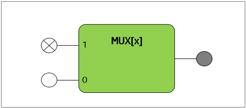
Figure 36. Multiplexer
Microphone Selector (MICSEL)
- Combines N number of channels at input into M number of channels at output
- Typically realizes down-mixing from N channels to 1 channel

Figure 37. Microphone Selector
Sample Rate Converter
- Performs Sample Rate Conversion
- Can be executed in either LL or DP domain
- Highly optimized implementation
Figure 38. Sample Rate Converter
Post Processing Modules
- Shim wraps 3rd party library
- Processing time depends on processing function
- Configured via generic module configuration API
- Processing can be disabled using generic call
Figure 39. Post Processing Modules
Module Interfaces
Module Instances
- A Module instance is a single processing unit.
- The maximum number of instances is declared per module during image configuration.
- A Module provides up to 8 input pins (aka sinks) and up to 8 output pins (aka Sources).
- A Module instance must be initialized before use.
- There is a base module configuration defined, common for all modules. It can be extended by a specific module (optional).
Module Instance Supported Calls
- Init Module Instance
- Config Parameter Get
- Config Parameter Set
- Set Processing State (On|Bypass)
- Enter/Exit Module Restore
For a full description of the supported calls, see Section 5.6 for full description of the Module Instance Supported Calls.
Implementing a new Module
{TBD}
Module API
You can find information about the Module API at Intel Audio FDK Module API.
While the Intel ADSP system provides some built-in processing modules for typical use cases, you can also extend its feature set with user-defined module packages. Such module packages are referred to as "loadable processing module" (or simply "loadable module") packages, because they can be loaded into the ADSP memory dynamically, as needed.
This section presents an overview of the Intel ADSP API.
Module implementation shall meet three minimum requirements:
- As a processing module class, it shall implement the ProcessingModuleInterface class.
- As a module factory class, it shall implement the ProcessingModuleFactoryInterface class.
- It shall declare itself as "loadable" with help of the macro DECLARE_LOADABLE_MODULE.
ProcessingModule Class
The ProcessingModuleInterface defines methods that the Intel ADSP System calls to configure and fire the stream processing.
The center of the development of a loadable module package is the Intel_adsp::ProcessingModuleInterface class. Every custom module must implement this class. The ProcessingModuleInterface defines methods that the Intel ADSP System calls to configure and fire the stream processing.
For convenience, the Intel_adsp::ProcessingModule class is provided as a partial default implementation of the ProcessingModuleInterface class. It is suitable for the usual needs of most modules, when the count of input and output module pins is known at compile time.
A custom module class needs to implement at least the following three functions:
- ProcessingModule::Process()
- ProcessingModule::SetConfiguration()
- ProcessingModule::SetProcessingMode()
ProcessingModule::Process()
Processes the stream buffers extracted from the input pins, and produces the resulting signal in the stream buffer of the output pins.
ProcessingModule::SetConfiguration()
Applies the upcoming configuration message for the given configuration ID.
ProcessingModule::SetProcessingMode()
Sets the processing mode for the module.
Optionally, the methods in the following sections can be overridden in ProcessingModule.
ProcessingModule::GetConfiguration()
Retrieves the configuration message for the given configuration ID.
ProcessingModule::Reset()
Upon call to this method, the Intel ADSP system requires the module to reset its internal state to a well-known initial value.
Parameters which may have been set through SetConfiguration() are expected to be left unchanged.
ProcessingModuleFactory class
As part of a custom module package, a process module factory shall be provided to handle creation of the custom processing module components. The ProcessingModuleFactoryInterface class defines requirements for this. The Create() method, on some parameters given by the ADSP system in the factory, is intended to provide the following:
- An initialized user-defined module instance
- The input and output pins associated to the module instance
- The stack buffer for execution of the module instance
You should implement the methods in the following sections.
ProcessingModuleFactory::Create()
Creates a RegisteredProcessingModule instance.
The custom implementation of the Create method is expected to handle initialization of the custom module instances.
ProcessingModuleFactory::GetPrerequisites()
Indicates the prerequisites for module instance creation.
The ADSP system calls this method before each module instance creation.
Tasks and Schedulers
To meet different task requirements for low latency domain tasks and processing tasks, the DSP scheduling uses separate scheduler levels.
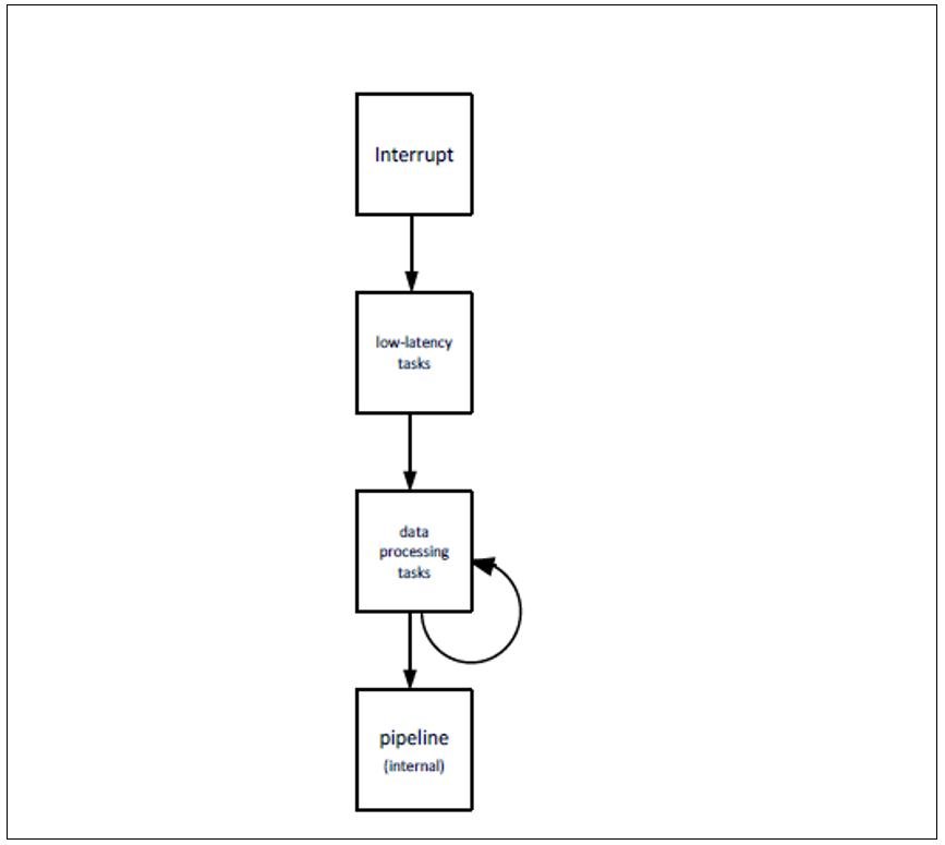
Figure 40. Scheduler Levels
The low latency scheduler and data processing scheduler are configured by the management service.
The management service receives a request to start a specific type of processing request. In the first step, the request must be split into tasks. The task list depends on the current DSP state (running tasks), and on configuration data (for example, post processing).
Each task must be looked up in the task database to obtain its parameters. The database may come from module metadata or a dedicated plug-in.
The management service sends the prepared topology (binding), allocated instances of memory blocks, and core assignment to DSP.
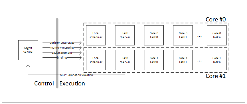
Figure 41. Scheduling between Management Service and Pipelines
Low Latency Task Scheduler
The low latency scheduler is a set of processing routines that walk through a required set of queues and bits.
From an overall scheduling perspective, the important parameter is the number of clock cycles consumed by the low latency domain. The remaining number of clock cycles is the budget that the data processing scheduler can use.
The number of CPU cycles consumed by the low latency domain depends on the number of active components. The management service uses post-implementation firmware performance data to estimate the amount of computing required by the low latency domain. The calculation considers fixed overhead, type of active blocks, number of instances, and (sometimes) parameters of instance.
Data Processing Task Scheduler
In DSP firmware, the number of possible stream configurations and combinations is enormous. It is enough to consider each stream parameter (such as decoder type, channel configuration, and sampling rate) that are set separately for each stream. Adding multiple extra decoders and post-/pre-processing modules makes a solution unmanageable.
Therefore, a major focus of the data processing scheduler is reducing the effort required to integrate and validate new processing modules. This goal is achieved by the following:
Each data processing pipeline contains a set of processing modules and ends with a real-time sink.
- Automated pipeline setup
- Flexible component binding
- Automatic buffer calculation
- Setting up schedule
- Resource requirement calculation
- Pipeline separation
- Diagnostic feedback mechanism

Figure 42. Example of Data Processing pipeline
Figure 42 shows an example pipeline, consisting of three processing modules, intermediate buffers, and a real-time sink. Analysis of the playback pipeline starts from the end. The real-time sink consumes data sample groups (or ‘samples’) at the sampling frequency rate. In the Intel Quark SoC S1000 ASIC, all samples in a system tick interval is consumed by the low latency portion of the firmware within a system tick interval.
Each processing module is characterized by a set of configuration-dependent parameters:
- Block Size (BS) describes the nominal amount of data samples processed in single processing cycle
- Output Buffer Size (OBS) describes the output buffer space in samples that is required to run the module
- Input Buffer Size (IBS) describes the number of samples available at input that are required to run the module
- Block Processing Cost (BPC) describes the number of Core clocks required to process a single block
- This shall be the guaranteed worst case for any block, not the average number
Each audio streaming task needs to work in real time. As a result, we can assume that the overall DSP utilization must be guaranteed to be less than 100%. The management service task mapping must ensure that this is the case. With this assumption, it is possible to adopt derivative Earliest Deadline First (EDF) scheduling.
EDF has attractive properties in this situation for the following reasons:
-
Ability to schedule tasks up to 100% (theoretical) load
In theory, any combination of independent tasks will be scheduled once utilization is under 100%.
-
Algorithm simplicity (low cost)
The scheduler can always pick the first task from the active task list. The active task list is a sorted list of task deadlines. Scheduling a new deadline is a simple insertion task into the appropriate place on the list.
-
Dynamic scheduling
The algorithm can execute tasks back-to-back, consuming less than allocated time and allowing the core to go to low-power state. For comparison, in Synchronous Data Flow (SDF), if a task completes faster (which is common on DSP), the algorithm must wait until the start of the next scheduled task.
-
Reduced number of context switches
This is due to a lack of fairness: for example, using round robin algorithm limits the number of task switches. It always executes the first task from the list until it is complete. This happens even when the next task on the list has the same deadline.
Memory Map
The 4 MB of internal high performance memory is the central memory block for the Intel Quark SoC S1000 ASIC. The dual DSP cores and GNA engine can access this central memory. This high performance internal memory is used as workspace for the DSP core with firmware code and data, samples from the audio streams, speech scoring models used by the GNA Engine, and so on.
The 64 kB of low power memory is attached to the low power Memory Fabric domain, where LP SRAMs are located. The DSP cores use this memory mainly for DMA buffers.
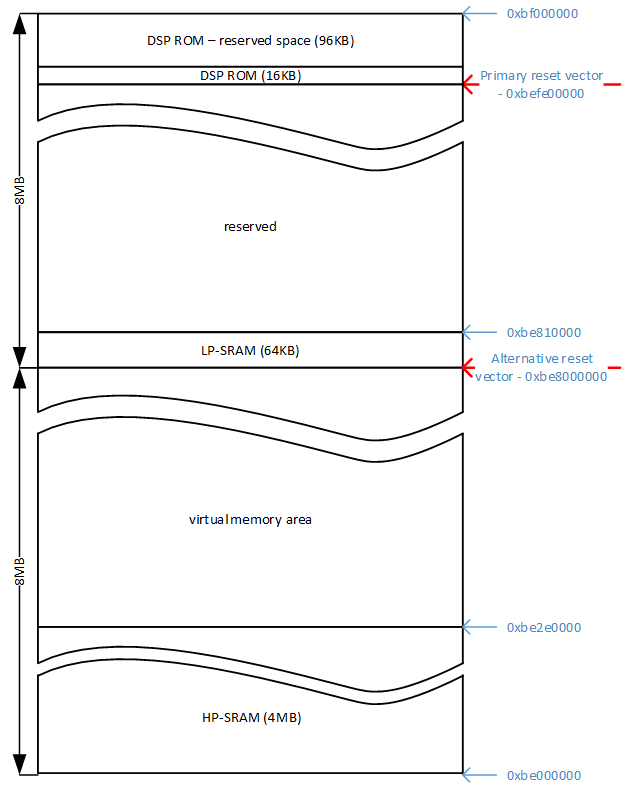
All allocation requests refer to virtual memory address space. Even DMA drivers allocating buffers for DMA operations do not require continuous physical memory since VA/PA translation mechanism includes also DMA transactions.

Figure 43. Virtual memory allocation example
Figure 43 depicts example of virtual memory allocation for the firmware image. In generic case firmware image may contain:
- Base firmware (including initialization)
- Libraries
- Large module instance data area
- Pipeline data areas
- Optional 3rd party library areas
Base firmware contains base runtime infrastructure and minimum set of modules that are linked into typical three sections: code, read-only data and bss.
Firmware libraries can contain one or more modules, module parameters are described in library manifest.
Last part of the image is bss area used to keep module instance data. Instance data contains all memory areas required by module instance including: persistent memory, scratch area (due to preemptive scheduling scratch area cannot be shared) and thread stack. Modules using large instance data (> 32KB) have instance data allocated in this area. Each module has allocated maximum instances of maximum size as indicated in module entry.
Instance data of modules consuming less space are allocated in pipeline areas. There is fixed amount of pipelines with predefined size that given firmware image configuration may support.
This scheme of allocation is designed to reduce memory allocation overhead and use of virtual address space: Large modules are natural way supported in limited amount of instances (typically 1 or 2). There may be much more small modules and page alignment on each allocated area would be expensive. Inter-module queues fall also into category of small areas. All memory within pipeline area is allocated linear way, it is freed altogether with destroying pipeline.
Stream and Pipeline Management
Pipeline Overview
- A pipeline is a set of module instances, in the processing order
- The pipeline allocates tasks (LL and DP) as execution context for module instances
- The pipeline allocates queues between module instances (DP queues are sharable between cores)
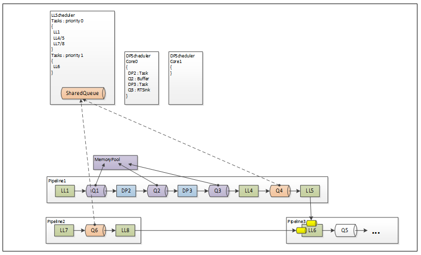
Figure 44. Pipeline
Pipeline Attributes
Static
- ID (init parameter) is unique within the system
- Priority (init parameter) determines the order of execution in LL domain (0 – highest, 7 – lowest)
- Memory pool size
Runtime
- State (propagated to modules/tasks/queues etc.)
Pipeline Messages
A pipeline supports the following messages:
- CreatePipeline
- DeletePipeline
- SetPipelineState
- GetPipelineState
For a full description of pipeline supported messages, see Pipeline Management IPC
Pipeline States
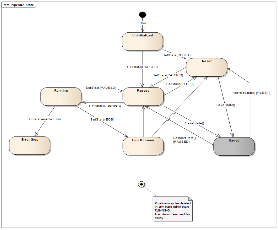
Figure 45. Pipeline State Machine
Uninitialized
This is initial state of the pipeline when it is created. The pipeline remains in this state while modules are instantiated and added. Other than setting another state, no other information comes from software that this process is completed. Therefore, an exit from this state triggers the creation and registration of the pipeline’s tasks.
Moreover, to ensure consistent state transition sequence, the Reset state is set internally immediately after all tasks are registered. It means that IPC_PplSetState(Reset) triggers the Uninitialized → Reset sequence, while IPC_PplSetState(Paused) triggers the Uninitialized → Reset → Paused sequence.
Reset
When the pipeline enters the Reset state, all associated tasks and module instances are reinitialized by propagating the new state to their SetPplState() methods.
The state of the queues allocated by the pipeline for data exchange of LL/DP tasks is also reset.
Paused
The Paused state is propagated to all associated tasks and modules instances to deactivate them and exclude them from scheduling.
Running
The Running state is propagated to all associated tasks and module instances to make them schedulable again.
EndOfStream
The EndOfStream state is valid for the Decode pipeline type only.
This state is saved inside the pipeline object but is not propagated to tasks. All associated tasks and module instances should continue their normal operations until an underrun is detected by the MixIn module instance. Detecting underrun when the parent pipeline enters the EndOfStream state triggers a special flow, which is documented in "End of Stream Notification”.
ErrorStop
The ErrorStop state is propagated to all associated tasks and module instances to deactivate them when an unrecoverable error occurs inside the pipeline.
[Saved]
This state is propagated to the pipeline components internally by the Pipeline::Save() method, to save module instances and context information of tasks. The Pipeline Manager also returns this value in response to IPC_PplGetState if the specified pipeline ID points to a pipeline that was stored in the host memory.
The current state of the pipeline is not changed.
[Restored]
This state is propagated to the pipeline components internally by the Pipeline::Restore() method to restore context information and reconnect to HW components.
Driver Interfaces
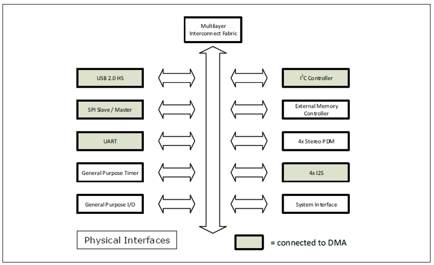
Figure 46. Physical Interfaces
The physical interfaces include the following:
- A USB 2.0 HS device interface
- A slave SPI interface connects to a master host MCU or AP
- A master SPI interface can be used to connect audio codec or memory devices
- An I2C interface connects to off-chip components such as codecs and PMICs
- A UART interface for debug
- Four i2s interfaces connect to a microphone array, a speaker codec, the host processor, and a radio
- Four stereo PDM interfaces can be used to connect up to eight PDM microphones
- 26 general-purpose I/O signals connect to platform controls and status indicators such as LEDs and power switches
- A parallel memory interface connects to off-chip memories of up to 8 MB
- System interface includes asynchronous reset, wake-up, interrupt request, crystal oscillator power-down, and clock outputs and crystal
GNA (GMM and Neural Network Accelerator) Engine
This section describes the application-facing API for the GNA accelerator in the Intel Quark SoC S1000 ASIC.
API Definition
Data Structures
gna_device
Description
This structure is created during the module initialization process. It provides access to internal data (MMIO, irq resource, and so on) and is a mandatory argument of the GNA firmware API function calls.
Syntax
From the firmware level (GNA module code), access to this structure’s instance can be obtained through the module’s private field. The module initialization routine is responsible for preparing the gna_device structure. The following snippet takes care of gna_device initialization.
gna_device_attributes attrs;
gna_device_attributes_init(&attrs, DSP_MS_GNA_BA, EMPTY_IRQ_RESOURCE);
gna_device_init(&this->gna_, &attrs);
gna_request
Description
This structure must be passed to every calculation call. It ties a unique request identifier with input/output buffers and the model to be used for scoring.
Syntax
struct gna_request
{
uint16_t request_id;
int16_t *inputs;
int16_t *outputs;
void *model;
};
Members
request_id
Unique identifier assigned by the client application to recognize the request later.
inputs
Pointer to the buffer containing inputs for the neural network. The buffer should be allocated in DSP memory space and 64-byte aligned in both location and size.
outputs
Pointer to the output buffer. The calculation results appear there. The buffer should be allocated in DSP memory space and 64-byte aligned in both location and size.
model
Pointer to the model image to be used for scoring this request. Should be allocated in DSP memory space, 64-byte aligned in location and size, and populated with the model image data.
Functions
gna_device_model_setup
Description
Sets up the model in GNA’s configuration. Every model, after loading to memory, must be configured. The model image is described by GNA’s MMU entries. Model loading to DSP memory space is outside of the scope of this API.
Syntax
ECODE gna_device_model_setup(
struct gna_device *self,
void *model);
Parameters
self
This is gna_device structure. It provides access to configuration details, which are filled on the function call.
model
Pointer to the space where model data begins. Should be 64-byte aligned in location. The size is inferred from the header present inside the model image.
gna_device_calculate
Description
Sets up the model in GNA’s configuration. Every model, after loading to memory, must be configured. The model image is described by GNA’s MMU entries. Model loading to DSP memory space is outside of the scope of this API.
Syntax
ECODE gna_device_calculate(
struct gna_device *self,
struct gna_request *request);
Parameters
self
This is gna_device structure.
request
Structure describing the request.
gna_device_get_status
Description
Returned ECODE provides basic information about the status: success, in progress, failed, or in queue. If the returned value indicates success, it is safe to inspect the scoring results in the output buffer. In case of failure, additional information can be obtained by inspecting the request_status output parameter.
Syntax
ECODE gna_device_get_status(
struct gna_device *self,
uint16_t request_id,
uint32_t *request_status);
Parameters
self
This is gna_device structure.
request_id
Unique identifier of the request we are waiting for.
request_status
If the request is not still in queue, this will get filled with the value of GNA’s status register.
Sample Usage Model
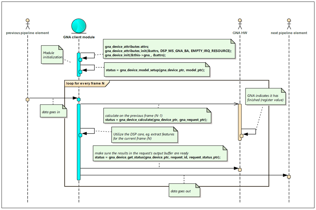
Figure 47. Sample Usage Model
I2C Interface
[TBD]
API Definition
Definitions
Constants
Syntax
#define IC_TX_BUFFER_DEPTH 8
#define IC_RX_BUFFER_DEPTH 8
#define IC_EMPTYFIFO_HOLD_MASTER_EN 1
#define IC_FIRST_DATA_BYTE_STATUS 1
#define IC_RX_FULL_HLD_BUS_EN 1
#define I2C_DYNAMIC_TAR_UPDATE 1
#define IC_BUS_CLEAR_FEATURE 1
#define IC_RESTART_EN 1
#define IC_SMBUS 0
#define IC_DEVICE_ID 0
#define PIN_MUXING 1
i2c_transfer_flags
Description
I2C transfer flags.
Syntax
typedef enum {
    I2C_MASTER_TRANSFER_NORMAL=0,
    I2C_MASTER_TRANSFER_GENERAL_CALL=1
} i2c_transfer_flags;
i2c_device_speed
Description
I2C device speed flags.
Syntax
typedef enum {
    I2C_MASTER_DEVICE_SPEED_STANDARD = 1,
    I2C_MASTER_DEVICE_SPEED_FAST,
    I2C_MASTER_DEVICE_SPEED_HIGH
} i2c_device_speed;
I2C_MASTER_DEVICE_SPEED_HIGH - not supported, IC_MAX_SPEED_MOD=2
i2c_device_operation
Description
I2C device operation flags.
Syntax
typedef enum {
    I2C_MASTER_DEVICE_OP_WRITE=0,
    I2C_MASTER_DEVICE_OP_READ=1
} i2c_device_operation;
i2c_addressing_option
Description
I2C addressing option flags.
Syntax
typedef enum {
    I2C_MASTER_DEVICE_ADDR_10_BIT,
    I2C_MASTER_DEVICE_ADDR_7_BIT
} i2c_addressing_option;
pfn_i2c_master_device_workitem_done
Description
I2C master workitem completion callback.
Syntax
typedef void (*pfn_i2c_master_device_workitem_done)(
    struct i2c_master_device_workitem* self,
    void* context,
    ErrorCode error_code);
self - pointer to I2C workitem that has completed.
context - Client supplied callback context.
error_code - Reason why the workitem has finished.
pfn_gpdma_transfer_i2c_xblock_done
Description
I2C master GP DMA transfer block completion callback.
Syntax
typedef void (*pfn_gpdma_transfer_i2c_xblock_done)(
    struct gpdma_transfer_i2c_xblock* self,
    void* context,
    ErrorCode error_code);
self - pointer to I2C block that has completed.
Context - Client supplied callback context.
error_code - Reason why the block has finished.
Structures
i2c_master_device_workitem
Description
I2C master device workitem.
Bare I2C master executes workitems in interrupt mode. Higher level objects like gpdma_transfer_i2c may be created to execute series of workitems also over GP DMA.
This object must be initialized in client-maintained buffer using i2c_master_device_workitem_init().
Then, client shall insert read/write commands to the buffer up to the buffer capacity.
Syntax
struct i2c_master_device_workitem
{
    pfn_i2c_master_device_workitem_done cb_done_;
    void* cb_done_context_;
    uint16_t slave_address_;
    uint8_t slave_10bit_addr_en;
    uint8_t transfer_flags_;
    uint32_t cmd_buffer_size_;
    uint16_t tx_commands_count_;
    uint16_t rx_commands_count_;
    uint32_t progress;
    uint32_t reads_done;
    ErrorCode tx_status;
    IC_DATA_CMD commands_[];
};
transfer_flags_ - for example, always restart
cmd_buffer_size_ - buffer for storing commands and received data
progress - field for command exeucuting progress save
reads_done - field for saving buffer write position
commands_ - contains TX commands up to index tx_commands_count_
i2c_master_device_attributes
Description
I2C master device initialization attributes.
Caller initializes this structure with a call to i2c_master_device_attributes_init() then applies desired configuration and finally passes it to i2c_master_device_init().
Syntax
struct i2c_master_device_attributes
{
    regs mmio_;
    void* i2c_mux_register_;
    irq_resource irq_;

    i2c_device_speed speed_;
    uint8_t restart_en_;
    uint8_t slave_disable_;
    uint8_t master_mode_;
    uint8_t ten_bit_addr_mode_;

    uint8_t bus_clr_feature_ctrl_;
    uint8_t stop_det_if_master_active_;

    uint8_t rx_fifo_full_hld_ctrl_;
    uint8_t tx_empty_ctrl_;

    uint8_t rx_fifo_tl_;
    uint8_t tx_fifo_tl_;

    uint32_t scl_low_timoeout_;
    uint32_t sdl_low_timoeout_;

    uint32_t SDA_RX_HOLD_;
    uint32_t SDA_TX_HOLD_;
    uint32_t tx_handshake_line_;
    uint32_t rx_handshake_line_;
};
i2c_master_device
Description
Bare metal I2C master device.
May transfer a single i2c_master_device_workitem in PIO/interrupt mode. DMA transfer over I2C is implemented in gpdma_transfer_i2c.
Syntax
struct i2c_master_device
{
    struct device_node device_;
    i2c_addressing_option addressing_;
    struct i2c_master_device_workitem* workitem_;
    uint32_t tx_handshake_line_;
    uint32_t rx_handshake_line_;

    uint32_t flushed_tx_cnt;
    uint32_t rx_full_ints;
};
gpdma_transfer_i2c_xblock
Description
I2C master device transfer block for #gpdma_transfer_i2c.
Syntax
struct gpdma_transfer_i2c_xblock
{
    dllist list_;
    LinkedList tx_descriptor_;
    LinkedList rx_descriptor_;
    pfn_gpdma_transfer_i2c_xblock_done cb_dma_done_;
    void* cb_dma_done_context_;
    struct i2c_master_device_workitem workitem_;

    ErrorCode transfer_status;
};
gpdma_transfer_i2c
Description
I2C master GP DMA transfer component.
This utility may be used to enqueue series of transfers to various I2C slaves using GP DMA.
Syntax
struct gpdma_transfer_i2c
{
    struct i2c_master_device* i2c_master_;
    struct dllist* xblock_head_;
};
Functions
i2c_master_clockgate_and_disable
Description
Clockgate and disable device.
Syntax
void i2c_master_clockgate_and_disable();
i2c_master_device_workitem_init
Description
Initializes I2C workitem in a buffer.
Capacity of the workitem results from subtracting workitem header size from the buffer_size and dividing that by size of command (2 bytes).
Returns a pointer to the workitem or NULL on failure.
Syntax
ErrorCode i2c_master_device_workitem_init(
        struct i2c_master_device_workitem* workitem,
                uint32_t buffer_size,
                uint32_t slave_address,
                uint8_t slave_10bit_addr_en,
                pfn_i2c_master_device_workitem_done cb_done,
                void* cb_done_context);
buffer - Buffer to be used for I2C workitem.
buffer_size - Size of buffer in bytes.
slave_address - Destination slave address.
cb_done - Completion callback pointer.
cb_done_context - Context to be passed to the completion callback.
i2c_master_device_workitem_write
Description
Appends register write operation to I2C workitem.
Syntax
ErrorCode i2c_master_device_workitem_write(
    struct i2c_master_device_workitem* self,
    uint8_t value);
self - Pointer to I2C workitem.
i2c_master_device_workitem_read
Description
Appends series of register read operations to I2C workitem.
Returns success or ADSP_NO_MORE_ENTRIES if workitem has no more capacity to hold requested operation.
Syntax
ErrorCode i2c_master_device_workitem_read(
    struct i2c_master_device_workitem* self,
    uint16_t bytes_to_read);
self - Pointer to I2C workitem.
bytes_to_read - Read length.
i2c_master_device_workitem_get_rx_byte
Description
Get response byte after workitem has been executed.
Returns success or ADSP_NO_MORE_ENTRIES if requested offset is beyond the workitem.
Syntax
ErrorCode i2c_master_device_workitem_get_rx_byte(
    struct i2c_master_device_workitem* self,
    uint16_t offset,
    uint8_t* value);
self - Pointer to I2C workitem.
offset - Number of read operation which result should be returned.
value - Pointer of location to store the result.
i2c_master_device_attributes_init
Description
Initializes I2C master device attributes.
Syntax
ErrorCode i2c_master_device_attributes_init(
    struct i2c_master_device_attributes* self,
    regs mmio,
    irq_resource irq);
self - Pointer to I2C master device initialization attributes.
mmio - pointer to I2C master device register space
irq - I2C master device interrupt resource
i2c_master_device_attributes_set_handshake
Description
Sets handshare.
Syntax
void i2c_master_device_attributes_set_handshake(
    struct i2c_master_device_attributes* self,
    uint32_t tx_handshake_line,
    uint32_t rx_handshake_line)
{
    self->tx_handshake_line_ = tx_handshake_line;
    self->rx_handshake_line_ = rx_handshake_line;
}
self - Pointer to I2C master device initialization attributes
tx_handshake_line – Transfer handshake line
rx_handshake_line – Receive handshake line
i2c_master_device_attributes_set_speed
Description
Sets speed.
Syntax
void i2c_master_device_attributes_set_speed(
    struct i2c_master_device_attributes* self,
    i2c_device_speed speed)
{
    self->speed_ = speed;
}
self Pointer to I2C master device initialization attributes.
speed - Speed
i2c_master_device_attributes_set_address_mode
Description
Sets address mode.
Syntax
ErrorCode i2c_master_device_attributes_set_address_mode(
    struct i2c_master_device_attributes* self,
    uint8_t address_mode);
self - Pointer to I2C master device initialization attributes
address_mode – Address mode
i2c_master_device_attributes_set_pin_mux_reg
Description
Sets ping mux reg.
Syntax
ErrorCode i2c_master_device_attributes_set_pin_mux_reg(
    struct i2c_master_device_attributes* self,
    void* pin_mux_reg);
self - Pointer to I2C master device initialization attributes
pin_mux_reg - Pointer to pin muxing global register
i2c_master_device_attributes_set_rx_tl
Description
Sets RX FIFO threshold.
Syntax
ErrorCode i2c_master_device_attributes_set_rx_tl(
    struct i2c_master_device_attributes* self,
    uint8_t rx_tl);
self - Pointer to I2C master device initialization attributes.
rx_tl - FIFO threshold
i2c_master_device_attributes_set_tx_tl
Description
Sets TX FIFO threshold.
Syntax
ErrorCode i2c_master_device_attributes_set_tx_tl(
    struct i2c_master_device_attributes* self,
    uint8_t tx_tl);
self - Pointer to I2C master device initialization attributes.
tx_tl - FIFO threshold
i2c_master_device_attributes_set_sda_hold
Description
Sets sda hold.
Syntax
inline ErrorCode i2c_master_device_attributes_set_sda_hold(
    struct i2c_master_device_attributes* self,
    uint32_t tx_sda,
    uint32_t rx_sda);
self Pointer to I2C master device initialization attributes.
tx_sda - TX SDA hold (unit of one ic_clk period)
rx_sda - RX SDA hold (unit of one ic_clk period)
i2c_master_device_attributes_scl_sdl_auto_recover
Description
Make I2C autonomously recover from SCL stuck at low condition.
Syntax
ErrorCode i2c_master_device_attributes_scl_sdl_auto_recover(
    struct i2c_master_device_attributes* self,
    uint32_t scl_low_timoeout,
    uint32_t sdl_low_timoeout);
self - Pointer to I2C master device initialization attributes.
scl_low_timeout – SCL low timeout
sdl_low_timeout – SDL low timeout
i2c_master_device_init
Description
I2C master device initialization.
Syntax
ErrorCode i2c_master_device_init(
    struct i2c_master_device* self,
    struct i2c_master_device_attributes* attributes);
self - pointer to caller-allocated buffer to store the device object.
attributes - Preconfigured attributes structure which may be discarded after init.
i2c_master_device_make_tx_port
Description
Make TX port.
Syntax
void i2c_master_device_make_tx_port(
    struct i2c_master_device* self,
    struct gpdma_peripheral_port* i2c_gpdma_tx);
i2c_master_device_make_rx_port
Description
Make RX port.
Syntax
void i2c_master_device_make_rx_port(
    struct i2c_master_device* self,
    struct gpdma_peripheral_port* i2c_gpdma_rx);
i2c_master_device_execute
Description
Requests I2C master to execute a transfer workitem.
Syntax
ErrorCode i2c_master_device_execute(
    struct i2c_master_device* self,
    struct i2c_master_device_workitem* workitem);
gpdma_transfer_i2c_xblock_write
Description
Appends register write operation to I2C GP DMA transfer block.
Returns success or error code if given xblock has no capacity to hold requested operation.
Syntax
ErrorCode gpdma_transfer_i2c_xblock_write(
    struct gpdma_transfer_i2c_xblock* self,
    uint8_t value);
gpdma_transfer_i2c_xblock_read
Description
Appends register read operation to I2C transfer.
Returns success or error code if given xblock has no capacity to hold requested operation.
Syntax
ErrorCode gpdma_transfer_i2c_xblock_read(
    struct gpdma_transfer_i2c_xblock* self,
    uint32_t bytes_to_read);
gpdma_transfer_i2c_xblock_get_rx_byte
Description
Get response byte after xblock has been executed.
Returns success or ADSP_NO_MORE_ENTRIES if requested offset is beyond the workitem.
Syntax
ErrorCode gpdma_transfer_i2c_xblock_get_rx_byte(
    struct gpdma_transfer_i2c_xblock* self,
    uint16_t offset,
    uint8_t* value);
self - Pointer to I2C workitem.
offset - Number of read operations for which result should be returned.
value - Pointer of location to store the result.
gpdma_transfer_i2c_xblock_next
Description
Iterates through I2C transfer for result inspection.
Returns:
- ADSP_SUCCESS if entry has been properly fetched,
- ADSP_NO_MORE_ENTRIES end of transfer has been reached.
Syntax
ErrorCode gpdma_transfer_i2c_xblock_next(
    struct gpdma_transfer_i2c_xblock* self,
    uint8_t* operation,
    uint16_t* register_address,
    uint8_t* data);
gpdma_transfer_i2c_xblock_init
Description
Initializes an empty I2C GP DMA transfer block in caller maintained buffer.
Capacity of the xblock results from subtracting xblock header size from the buffer_size and dividing that by size of command (2 bytes).
Returns xblock pointer or NULL on failure
Syntax
struct gpdma_transfer_i2c_xblock* gpdma_transfer_i2c_xblock_init(
         uint32_t buffer_size,
         uint16_t slave_address,
         uint32_t slave_10bit_addr_en,
         pfn_gpdma_transfer_i2c_xblock_done dma_cb_done,
         void* cb_dma_done_context_);
buffer - Buffer to be used.
buffer_size - Size of the buffer.
slave_address – Slave address
cb_done – Callback function
cb_done_context – Context
gpdma_transfer_i2c_init
Description
I2C init.
Syntax
ErrorCode gpdma_transfer_i2c_init(
    struct gpdma_transfer_i2c* self,
    struct i2c_master_device* i2c_master
    );
gpdma_transfer_i2c_enqueue_xblock
Description
I2C enqueue xblock.
Syntax
ErrorCode gpdma_transfer_i2c_enqueue_xblock(
    struct gpdma_transfer_i2c* self,
    struct gpdma_transfer_i2c_xblock* xblock);
gpdma_transfer_i2c_execute
Description
I2C execute.
Syntax
ErrorCode gpdma_transfer_i2c_execute(
    struct gpdma_transfer_i2c* self, gpdma_device* dma);
GPIO
[TBD]
API Definition
Definitions
Constants
Syntax
#define GPIO_PORTA 0
#define GPIO_PORTB 1
#define GPIO_PORTC 2
#define GPIO_PORTD 3
gpio_device_pin_mode
Description
GPIO pin mode.
Syntax
typedef enum {
    GPIO_PIN_MODE_INPUT,
    GPIO_PIN_MODE_OUTPUT
} gpio_device_pin_mode;
gpio_device_pin_level
Description
GPIO pin level.
Syntax
typedef enum {
    GPIO_PIN_LEVEL_LOW,
    GPIO_PIN_LEVEL_HIGH
} gpio_device_pin_level;
gpio_device_pin_irq_mode
Description
Interrupt sensitivity modes for GPIOs.
Syntax
typedef enum {
    GPIO_DEVICE_PIN_NO_IRQ,
    GPIO_DEVICE_PIN_IRQ_LOW,
    GPIO_DEVICE_PIN_IRQ_FALLING,
    GPIO_DEVICE_PIN_IRQ_HIGH,
    GPIO_DEVICE_PIN_IRQ_RISING,
    GPIO_DEVICE_PIN_IRQ_BOTH_EDGE,
} gpio_device_pin_irq_mode;
GPIO_DEVICE_PIN_NO_IRQ - GPIO pin no interrupt mode enabled
GPIO_DEVICE_PIN_IRQ_LOW - GPIO pin interrupt active-low mode
GPIO_DEVICE_PIN_IRQ_FALLING - GPIO pin interrupt falling-edge sensitive mode
GPIO_DEVICE_PIN_IRQ_HIGH - GPIO pin interrupt active-high mode
GPIO_DEVICE_PIN_IRQ_RISING - GPIO pin interrupt rising-edge sensitive mode
GPIO_DEVICE_PIN_IRQ_BOTH_EDGE - GPIO pin interrupt falling and falling edge sensitive mode
gpio_device_pin_attribute
Description
GPIO interrupt callback.
Syntax
typedef void (*pfn_gpio_interrupt)(
    void* context,
    struct gpio_device* gpio,
    uint8_t pin);
Structures
gpio_device_pin_attribute
Description
Initialization attributes of a GPIO pin.
Syntax
typedef void (*pfn_gpio_interrupt)(
    void* context,
    struct gpio_device* gpio,
    uint8_t pin);

struct gpio_device_pin_attribute
{
    uint8_t mode_ : 1;
    uint8_t level_ : 1;
    uint8_t irq_mode_ : 3;
    uint8_t pad_ : 4;
    pfn_gpio_interrupt cb_interrupt_;
    void* cb_interrupt_context_;
};
gpio_device_attributes
Description
GPIO device initialization attributes.
GPIO pin configuration is specified once at initialization according to the needs of particular board design and does not change later.
Structure must be initialized with gpio_device_attributes_init().
Syntax
struct gpio_device_attributes
{
    regs mmio_;
    irq_resource irq_;
    uint8_t ports_num_;
    uint8_t port_width_;
    struct gpio_device_pin_attribute pins_[GPIO_DEVICE_MAX_PORT_NUM][GPIO_DEVICE_MAX_PORT_WIDTH];
};
gpio_device_pin
Description
GPIO device single pin descriptor
Syntax
struct gpio_device_pin
{
    pfn_gpio_interrupt cb_interrupt_;
    void* cb_interrupt_context_;
};
gpio_device
Description
The gpio_device struct.
Syntax
struct gpio_device
{
    struct device_node device_;
    uint8_t ports_num_;
    uint8_t port_width_;
    struct gpio_device_pin pins_[GPIO_DEVICE_MAX_PORT_NUM][GPIO_DEVICE_MAX_PORT_WIDTH];
};
Functions
gpio_device_attributes_init
Description
Initializes GPIO device attributes.
All GPIOs are disabled by default. Use either of
- gpio_device_attributes_set_pin_mode_input(),
- gpio_device_attributes_set_pin_mode_output(),
- gpio_device_attributes_set_pin_mode_interrupt()
to select particular mode on specific GPIOs.
Syntax
ErrorCode gpio_device_attributes_init(
    struct gpio_device_attributes* self,
    regs mmio,
    irq_resource irq);
self - Pointer to GPIO device initialization attributes
mmio - pointer to GPIO device register space
irq - GPIO device interrupt resource
gpio_device_attributes_set_pin_mode_input
Description
Configures a GPIO as input.
Syntax
ErrorCode gpio_device_attributes_set_pin_mode_input(
    struct gpio_device_attributes* self,
    uint8_t port,
    uint8_t pin);
self - Pointer to GPIO device initialization attributes
port - GPIO port to be configured
pin - GPIO pin to be configured
gpio_device_attributes_set_pin_mode_interrupt
Description
Configures a GPIO as interrupt source.
Syntax
ErrorCode gpio_device_attributes_set_pin_mode_interrupt(
    struct gpio_device_attributes* self,
    uint8_t pin,
    pfn_gpio_interrupt interrupt_callback,
    void* interrupt_callback_context,
    gpio_device_pin_irq_mode irq_mode);
self - Pointer to GPIO device initialization attributes
pin - GPIO pin to be configured (PORTA pins support interrupt mode)
interrupt_callback - pointer of function to be called on GPIO interrupt
interrupt_callback_context - User specified context to be passed to interrupt_callback
irq_mode - Specifies kind of GPIO event that triggers interrupt
gpio_device_attributes_set_pin_mode_output
Description
Configures an output mode of GPIO pin.
Syntax
ErrorCode gpio_device_attributes_set_pin_mode_output(
    struct gpio_device_attributes* self,
    uint8_t port,
    uint8_t pin,
    gpio_device_pin_level initial_level);
self - Pointer to GPIO device initialization attributes
port - GPIO port to be configured
pin - GPIO pin to be configured
initial_level – Initial GPIO level
gpio_device_init
Description
GPIO device init function.
Syntax
ErrorCode gpio_device_init(
    struct gpio_device* self,
    struct gpio_device_attributes* attributes);
self - Pointer to GPIO device.
attributes - Preconfigured attributes structure which may be discarded after init.
gpio_device_pin_level gpio_device_pin_get_level
Description
Returns current level on gpio pin.
Syntax
enum gpio_device_irq_status { GPIO_DEVICE_PIN_IRQ_DISABLED, GPIO_DEVICE_PIN_IRQ_ENABLED };
gpio_device_pin_level gpio_device_pin_get_level(
    struct gpio_device* self,
    uint8_t port,
    uint8_t pin);
self - Pointer to GPIO device
port - GPIO port
pin - GPIO pin within port
gpio_device_pin_int_ctrl
Description
GPIO device pin int control.
Syntax
ErrorCode gpio_device_pin_int_ctrl(
    struct gpio_device* self,
    uint8_t pin,
    gpio_device_irq_status status);
self - Pointer to GPIO device
pin - GPIO pin (PORTA pins support interrupt mode)
status - Status
gpio_device_pin_set_output
Description
Set GPIO device pin output.
Syntax
ErrorCode gpio_device_pin_set_output(
    struct gpio_device* self,
    uint8_t port,
    uint8_t pin,
    gpio_device_pin_level level);
self - Pointer to GPIO device
port - GPIO port
pin - GPIO pin within port
level - Level
gpio_device_isr
Description
Syntax
void gpio_device_isr(
    struct gpio_device* self,
    irq_resource irq);
self - Pointer to GPIO device
irq – IRQ resource
UART
[TBD]
Building the Firmware
This section outlines the steps required to build the firmware. It addresses the setup of the host development environment, source code download, and build procedure. The development environment for building the firmware will be Windows. There is no support for Linux at this point.
Prerequisites
- Access to the quark-audio git repository: https://github.com/otcshare/quark-audio
- Access to Xtensa Development Environment installation executable: Xplorer-6.0.4-windows-installer.exe
- Access to X6H3SUE_2016_4_win32.tgz
Setting Up the Development Environment
Install Xtensa Development Environment
1. Install the Xtensa Development Environment by running the self-extracting executable Xplorer-6.0.4-windows-installer.exe Choose the default options.
Set Up the Network Configuration
2. Choose Window → Preferences → General → Network Connections
3. Set any required HTTP/HTTPS Proxy settings.
Create a New Xtensa Configuration
4. Choose File → New → Xtensa Configuration → Install a new build from downloaded bundle as the new configuration
5. Click Next.
6. In the next window, click Browse and select the file X6H3SUE_2016_4_win32.tgz Click Add Build. You should see something like the following picture.
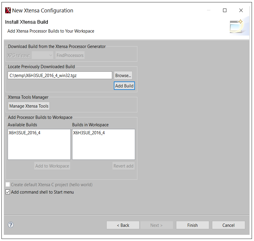
Figure 48. Create New Xtensa Configuration
7. Click Finish. The installer will take some time to complete, as it creates files.
Install the Xtensa License.
8. Choose Help → Xplorer License Keys → License Options → Install License Keys.
9. Insert the <port>@<server> and select Point to the selected license file in its current location.
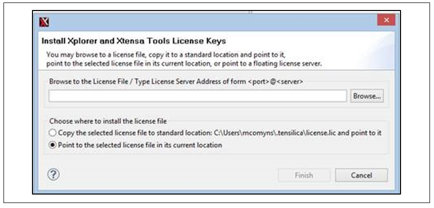
Figure 49. Install the Xtensa License
Building the Firmware
Download the Source Code
10. Open https://github.com/otcshare/quark-audio
11. Either download or clone the software.
Create a New Project
12. In the Xtensa Development GUI, press <CTRL>+N to create a new Unmanaged Xtensa C/C++ Project. Alternatively, go to File → New → Other → Unmanaged Xtensa C/C++ Project.
13. Set the location to the FW folder in which you cloned or unzipped the software.
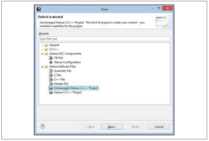
Figure 50. Create a New Xtensa Project (1)
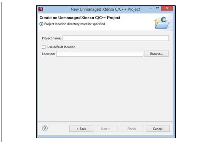
Figure 51. Create a New Xtensa Project (2)
Create Make Target
14. Right-click the project and choose Make Targets → Create
15. Enter the target name, as shown in the following figure.
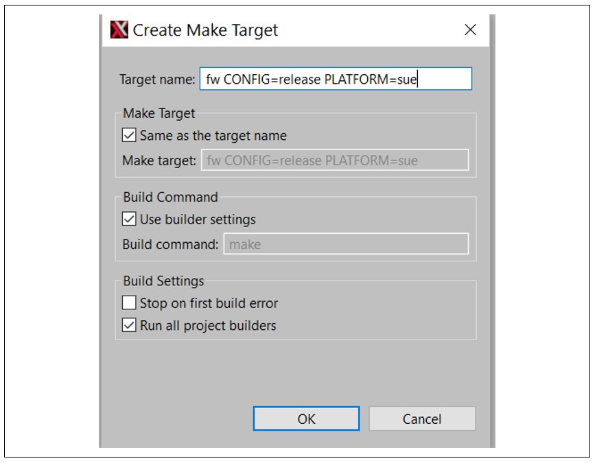
Figure 52. Create a Make Target
Build the Firmware Image
16. Choose Window → Show View → Make Target
17. Select Build Target. It takes about 10 minutes to build the first time.
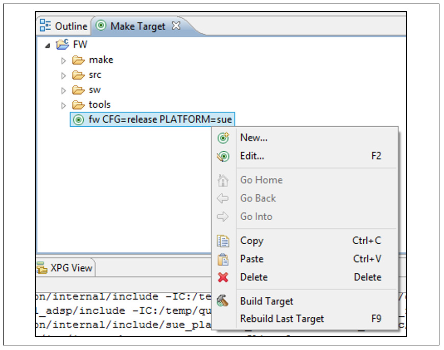
Figure 53. Build Firmware Image
Firmware Binary
There are three main parts of the Firmware Image Binary:
- Extended Manifest
- Manifest
- Firmware Binaries
Firmware Image Builder processes the content of firmware ELF files into a firmware binary using binmap files. The binmap files describe the layout of the firmware binary and contain information about firmware modules and their properties.
The structure of the binary image is identical for the Base FW and for libraries.
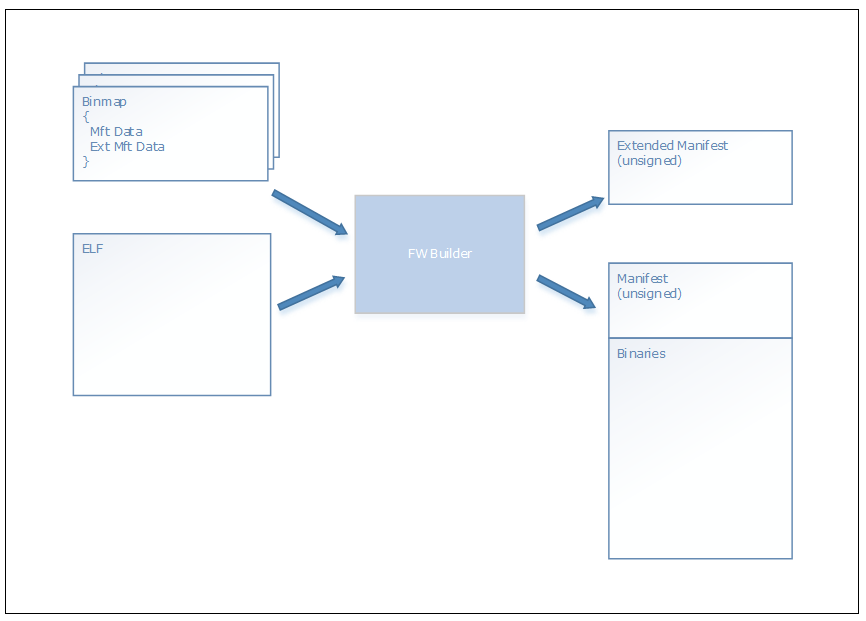
Figure 54. Firmware Binary Build Process
Firmware Image Extended Manifest
Firmware Image Extended Manifest begins with ExtendedManifestHeader followed by array of ExtendedModuleConfig entries.
ExtendedManifestHeader Structure
Syntax
struct ExtendedManifestHeader
{
    uint32_t  ext_manifest_id;
    uint32_t  ext_manifest_len;
    uint16_t  ext_manifest_version_major;
    uint16_t  ext_manifest_version_minor;
    uint32_t  ext_manifest_entries;
};
Members
ext_manifest_id
Extended manifest magic number. Set to “$AE1”.
ext_manifest_len
Size of extended manifest in bytes.
ext_manifest_version_major
Major version of extended manifest structure. Set to 1 for FDK 1.0.
ext_manifest_version_minor
Minor version of extended manifest structure. Set to 0 for FDK 1.0.
ext_manifest_entries
Number of extended manifest module entries.
ExtendedModuleConfig Structure
Each ExtendedModuleConfig structure is followed by array of SchedulingCapabilities and array of PinDescription entries.
Number of entries in the SchedulingCapabilities is specified by num_scheduling_capabilities.
Number of entries in the PinDescription array is specified by num_pin_entries.
Syntax
struct ExtendedModuleConfig
{
    uint32_t    ext_module_config_length;
    uint32_t    guid[4];
    uint16_t    version_major;
    uint16_t    version_minor;
    uint16_t    version_hotfix;
    uint16_t    version_build;
    ModuleType  module_type;
    uint32_t    init_settings_min_size;
    uint32_t    num_scheduling_capabilities;
    uint32_t    num_pin_entries;
};
Members
ext_module_config_length
Size of this extended module config in bytes.
guid
Module GUID.
version_major
Module version major.
version_minor
Module version minor.
version_hotfix
Module version hotfix.
version_build
Module version build.
module_type
Type of the module.
enum ModuleType
{
    BaseFwModule    = 0,
    MixInModule     = 1,
    MixOutModule    = 2,
    CopierModule    = 3,
    PeakVolModule   = 4,
    UpDwMixModule   = 5,
    MuxModule       = 6,
    SrcModule       = 7,
    WovModule       = 8,
    FxModule        = 9,
    AecModule       = 10,
    KpbModule       = 11,
    MicSelectModule = 12
};
init_settings_min_size
Minimum size of initialization settings.
num_scheduling_capabilities
Number of scheduling capabilities entries that follow ExtendedModuleConfig.
num_pin_entries
Number of pin description entries that follow scheduling capabilities array.
SchedulingCapability Structure
Syntax
struct SchedulingCapabilities
{
    uint16_t   frame_length;
    Multiples  multiples_supported;
};
Members
frame_length
Input frame length in Samples (sample groups).
multiples_supported
Supported frame length multiples.
Multiples Structure
Syntax
struct Multiples
{
    uint16_t x1 : 1;   // (base * 1)
    uint16_t x2 : 1;   // (base * 2)
    uint16_t x3 : 1;   // (base * 3)
    uint16_t x4 : 1;   // (base * 4)
    uint16_t x5 : 1;   // (base * 5)
    uint16_t x6 : 1;   // (base * 6)
    uint16_t x7 : 1;   // (base * 7)
    uint16_t x8 : 1;   // (base * 8)
    uint16_t x9 : 1;   // (base * 9)
    uint16_t x10 : 1;  // (base * 10)
    uint16_t x11 : 1;  // (base * 11)
    uint16_t x12 : 1;  // (base * 12)
    uint16_t x13 : 1;  // (base * 13)
    uint16_t x14 : 1;  // (base * 14)
    uint16_t x15 : 1;  // (base * 15)
    uint16_t all : 1;  // (base * X)
};
PinDescription Structure
Syntax
struct PinDescription
{
    PinCapabilities        capabilities;
    StreamType             format_type;
    SampleRates            supported_sample_per_second;
    SampleSizes            supported_valid_bits_per_samples;
    SampleContainers       supported_container_per_samples;
    ChannelConfigurations  supported_number_channels;
};
Members
capabilities
Pin capabilities.
format_type
Supported stream type.
enum StreamType
{
    Pcm = 0,
    Mp3 = 1,
    Aac = 2
};
supported_sample_per_second
Supporter sample rates.
struct SampleRates
{
    uint32_t freq_8000   : 1;
    uint32_t freq_11500  : 1;
    uint32_t freq_12000  : 1;
    uint32_t freq_16000  : 1;
    uint32_t freq_18900  : 1;
    uint32_t freq_22050  : 1;
    uint32_t freq_24000  : 1;
    uint32_t freq_32000  : 1;
    uint32_t freq_37800  : 1;
    uint32_t freq_44100  : 1;
    uint32_t freq_48000  : 1;
    uint32_t freq_64000  : 1;
    uint32_t freq_88200  : 1;
    uint32_t freq_96000  : 1;
    uint32_t freq_176400 : 1;
    uint32_t freq_192000 : 1;
    uint32_t reserved_   : 16;
};
supported_valid_bits_per_samples
Supported valid bits per sample.
struct SampleSizes
{
uint16_t bits_8 : 1;
uint16_t bits_16 : 1;
uint16_t bits_24 : 1;
uint16_t bits_32 : 1;
uint16_t bits_64 : 1;
uint16_t reserved_ : 11;
};
supported_container_per_samples
Supported bits per container.
typedef SampleContainers
{
uint16_t bits_8 : 1;
uint16_t bits_16 : 1;
uint16_t bits_32 : 1;
uint16_t bits_64 : 1;
uint16_t reserved_ : 12;
};
supported_number_channels
Supported channel configuration.
struct ChannelConfigurations
{
// FRONT_CENTER
uint32_t channel_mono : 1;
// FRONT_LEFT | BACK_LEFT
uint32_t channel_dual_mono : 1;
// FRONT_LEFT | FRONT_RIGHT
uint32_t channel_stereo : 1;
// FRONT_LEFT | FRONT_RIGHT | LOW_FREQUENCY
uint32_t channel_2_1 : 1;
// FRONT_LEFT | FRONT_RIGHT | FRONT_CENTER
uint32_t channel_3_0 : 1;
// FRONT_LEFT | FRONT_RIGHT | BACK_LEFT | BACK_RIGHT
uint32_t channel_quad : 1;
// FRONT_LEFT | FRONT_RIGHT | FRONT_CENTER | BACK_CENTER
uint32_t channel_surround : 1;
// FRONT_LEFT | FRONT_RIGHT | FRONT_CENTER | LOW_FREQUENCY
uint32_t channel_3_1 : 1;
// FRONT_LEFT | FRONT_RIGHT | FRONT_CENTER
// | BACK_LEFT | BACK_RIGHT
uint32_t channel_5_0 : 1;
// FRONT_LEFT | FRONT_RIGHT | FRONT_CENTER
// | SIDE_LEFT | SIDE_RIGHT
uint32_t channel_5_0_surround : 1;
// FRONT_LEFT | FRONT_RIGHT | FRONT_CENTER
// | LOW_FREQUENCY | BACK_LEFT | BACK_RIGHT
uint32_t channel_5_1 : 1;
// FRONT_LEFT | FRONT_RIGHT | FRONT_CENTER
// | LOW_FREQUENCY | SIDE_LEFT | SIDE_RIGHT
uint32_t channel_5_1_surround : 1;
// FRONT_LEFT | FRONT_RIGHT | FRONT_CENTER
// | BACK_LEFT | BACK_RIGHT | FRONT_LEFT_OF_CENTER
// | FRONT_RIGHT_OF_CENTER
uint32_t channel_7_0 : 1;
// FRONT_LEFT | FRONT_RIGHT | FRONT_CENTER
// | BACK_LEFT | BACK_RIGHT | SIDE_LEFT | SIDE_RIGHT
uint32_t channel_7_0_surround : 1;
// FRONT_LEFT | FRONT_RIGHT | FRONT_CENTER
// | LOW_FREQUENCY | BACK_LEFT | BACK_RIGHT
// | FRONT_LEFT_OF_CENTER | FRONT_RIGHT_OF_CENTER
uint32_t channel_7_1 : 1;
// FRONT_LEFT | FRONT_RIGHT | FRONT_CENTER
// | LOW_FREQUENCY | BACK_LEFT | BACK_RIGHT
// | SIDE_LEFT | SIDE_RIGHT
uint32_t channel_7_1_surround : 1;
uint32_t reserved_ : 16;
};
PinCapabilities Structure
Syntax
struct PinCapabilities
{
uint16_t direction : 1;
uint16_t reserved_ : 15;
};
Members
direction
Specifies direction of the pin, either
input (0),
output (1).
Firmware Image Manifest
This section documents the layout of the Firmware Image Manifest. The layout of the firmware image binary and the layout of the top-level firmware image manifest structures are platform-specific. However, most structures are common for all platforms. Therefore, this section contains both common and platform-specific subsections.
Firmware Image Layout
The firmware image binary for audio DSP begins with {TBD} followed by the AdspFwBinaryHeader structure that begins area the relevant for the management service.
AdspFwBinaryHeader can be found at offset 0x2000 in the image binary file.
Common Structures
AdspFwBinaryHeader Structure
Syntax
struct AdspFwBinaryHeader
{
uint32_t header_id;
uint32_t header_len;
uint8_t name[8];
uint32_t preload_page_count;
FwImgFlags fw_image_flags;
uint32_t feature_mask;
uint16_t major_version;
uint16_t minor_version;
uint16_t hotfix_version;
uint16_t build_version;
uint32_t num_module_entries;
uint32_t hw_buf_base_addr;
uint32_t hw_buf_length;
uint32_t load_offset;
};
Members
header_id
Set to “$AM1”,
header_len
Set to sizeof(AdspFwBinaryHeader) in bytes; using this value, ROM knows where the Module Entry array starts even if structure was altered after ROM release,
name
Set to the name of the image; this field is not used by the ROM,
preload_page_count
Size of the beginning of binary that should be loaded by the management service.
It is set to:
- Main image:
- Total size of the binary’s .text and .rodata
- Library image:
- Total size of the library’s .text and .rodata
fw_image_flags
Contains firmware Image flags set by the Firmware Image Builder.
feature_mask
Set to the mask of features provided by the firmware image.
major_version, minor_version, hotfix_version, and build_version
Updated by the build system.
num_module_entries
Set to number of entries in the module_entries array.
hw_buf_base_addr
Set to the base address of HW buffers area.
hw_buf_len
Set to the length of the HW buffers area.
Remarks
Even after a ROM release, the layout of the structure may be modified only within the part that starts after the num_module_entries field. This part is skipped by the ROM, and the ROM uses header_len to detect the actual structure size.
ModuleEntry Structure
Syntax
struct ModuleEntry
{
uint32_t struct_id;
uint8_t name[8];
uint32_t uuid[4];
ModuleType type;
uint8_t hash[DEFAULT_HASH_SHA256_LEN];
uint32_t entry_point;
uint16_t cfg_offset;
uint16_t cfg_count;
uint32_t affinity_mask;
uint16_t instance_max_count;
uint16_t instance_bss_size;
SegmentDesc segments[3];
};
Members
struct_id
Set to “$AME”.
name
Set to text identifier of the module. This field is not interpreted by firmware. It is used currently only to improve readability of the manifest binary.
uuid
Set to a unique identifier. This field is not used by firmware.
type
See ModuleType structure.
hash
Set to SHA-256 hash of the content of all loadable module segments declared in segments.
entry_point
Set to address of module’s entry point.
cfg_offset
Set to index of entry in module_config that begins sub array of configuration entries associated with the module. Firmware does not use this field as the configuration is always received from the management service as part of Init Module Instance IPC message.
cfg_count
Set to count of configuration entries in sub array of configuration entries associated with the module. Firmware does not use this field.
affinity_mask
Set to mask of cores that the module is allowed to run on. i-th bit in the mask set to 1 means that instances of this module are allowed to run on Core i.
instance_max_count
Maximum number of instances.
instance_bss_size
Maximum size (in 4KB pages) of .bss that may be allocated by a single module instance. Actual size of .bss may be smaller and depends on module instance configuration. Total .bss segment size set in 2-nd entry of segments array must be set to instance_max_count * instance_bss_size to be consistent.
segments
Contains descriptors for all module’s segments.
ModuleType Structure
Syntax
struct ModuleType
{
uint32_t load_type : 4;
uint32_t auto_start : 1;
uint32_t domain_ll : 1;
uint32_t domain_dp : 1;
uint32_t lib_code : 1;
uint32_t rsvd_ : 24;
};
Members
load_type
Indicates built-in module (0) or loadable (1).
auto_start
Indicates whether a module instance of the module should be created automatically (with no parent pipeline attached) at the Base FW startup.
domain_ll
Indicates whether a module instance can be executed in LL domain.
domain_dp
Indicates whether a module instance can be executed in DP domain.
lib_code
Indicates whether a module serves as a container for library code. Such a module is loaded by the management service but cannot be instantiated. There is no entry point defined neither other instance properties.
SegmentDesc Structure
Syntax
struct SegmentDesc
{
SegmentFlags flags;
uint32_t v_base_addr;
uint32_t file_offset;
};
union SegmentFlags
{
uint32_t ul;
struct
{
uint32_t contents : 1;
uint32_t alloc : 1;
uint32_t load : 1;
uint32_t readonly : 1;
uint32_t code : 1;
uint32_t data : 1;
uint32_t _rsvd0 : 2;
uint32_t type : 4;
uint32_t _rsvd1 : 4;
uint32_t length : 16;
} r;
};
Members
flags.type
Set to type of segment. One of ST_TEXT (0), ST_RODATA (1), or ST_BSS (2). Since .text segment is expected to be described by the first entry, .rodata is expected to be described by the second entry and so on, the type value should equal the index of entry in segments array.
flags.length
Length of segment in pages. Page size is 4KB.
v_base_addr
Set to virtual address of segment.
ModuleConfig Structure
Syntax
struct ModuleConfig
{
uint32_t par[4];
uint32_t is_pages;
uint32_t cps;
uint32_t ibs;
uint32_t obs;
uint32_t module_flags;
uint32_t cpc;
uint32_t obls;
};
Members
par
Configuration lookup parameters used by the management service [if exists].
is_pages
Number of bytes (not pages as the historical name suggests) required by the module instance if configured by this set of parameters.
cps
Number of DSP cycles consumed by the module instance to process one second of data.
ibs
Input buffer size expressed in sample groups (a sample group is a set of samples for all channels, for example, for 48kHz stereo signal there are 48 sample groups per millisecond and 96 samples per millisecond).
In case of modules that are instantiated in LL domain or designed to work with 1ms based frame size ibs is set to 1.
obs
Output buffer size expressed in sample groups.
module_flags
Reserved for future use.
cpc
Number of DSP cycles required to process chunk of data of ibs size.
obls
Output block size (reserved for future use).
Firmware Builder Input Files
The firmware builder reads the description of the layout of the firmware binary image from binmap-s.
This section documents the format of the binmap files.
Number Format
All number values in binmaps are specified in hex form (without the leading 0x) for parameters of mod_cfg entries, which are specified in decimal form.
Binmap Preprocessing
Comments
Binmap files may include single line comments put in a line that begins with #. The binmap preprocessor skips these lines.
Example
# This is a single line comment.
Includes
A binmap may use the include directive to include another binmap.
Syntax
include <another_binmap_file_path>
The file path may be either relative or absolute. The former approach is recommended to make the binmaps OS independent.
Example
include <another_binmap_file_path>
Defines
A binmap may define an identifier and assign a value to it.
Syntax
define <identifier> <value>
Example
define $PLATFORM SKU2
Binmap Processing
Numbers
All numbers, except for module configuration entries, should be specified in hexadecimal form (without the leading 0x specifier).
Strings
No quotes are used in a string specification. A multiword string containing spaces is read till the end of the line.
Example
# Pretty name of the module (“Up Down Mixer”)
name Up Down Mixer
Structure of Binmap
ADSP Binary Header Data
Syntax
binary_name <name>
Pretty name of the binary, max 8 characters long.
binary_ver 1.5|1.8
Version of the binary manifest and layout.
hw_buf_ba <base address>
Base address of HW buffers section in DSP memory.
This item is valid for 1.5 version only.
hw_buf_size <size in bytes>
Size of HW buffers section.
This item is valid for 1.5 version only.
max_data <size in bytes>
Maximum size of .data section that may be present in the input firmware ELF image.
This option should be used only for debug purpose when linking experimental, not fully-compliant code, as the .data section is not included in the output binary and is not loaded to the target DSP memory.
This parameter must be set to 0 for production image.
dyn_mem <section name>
Specifies a section defined by the input ELF file that has no content and is dynamically allocated by the firmware. This is so the address space assigned for that section is not included in any module’s address space. However, it is included in the computation of virtual memory area reserved for the image (the result of the computation is written by the builder to the PKG file).
Example
binary_name ADSPFW
binary_ver 1.5
hw_buf_ba be050000
hw_buf_size 4a000
max_data 0
Module Entry & Module Config Data
Specification of each module entry begins with general parameters followed by:
- A list of section groups that delivers data for ModuleEntry::segments[]
- A list of input and output pins and their capabilities
- Module configuration entries that deliver data for the module configuration table
Syntax
module <depl_type> <short_name>
This keyword begins a new section for each module.
<depl_type> specifies deployment type of the module, it is one of (see also Remarks):
b – Built-in module
d – Discrete mandatory module
o – Discrete optional module
l – Internal module in a library, contains library code and is never instantiated (does not have entry point defined and so on). Such a module serves as a container for section groups and does not need any of other module parameters listed below. Builder sets ModuleType::lib_code bit to 1 for this kind of module.
<short_name> specifies a short name of the module that appears in the FM Image Manifest, max 8 characters long.
uuid <uuid_value>
Unique identifier of the module (known also as GUID in Windows documentation).
name <pretty_name>
Pretty name of the module. It does not appear in the Firmware Image Manifest.
ver <ver_string>
Version of the module. It does not appear in the Firmware Image Manifest.
This item is optional.
type <mod_func_type>
Functional type of the module, one of:
- BaseFwModule (0),
- MixInModule (1),
- MixOutModule (2),
- CopierModule (3),
- PeakVolModule (4),
- UpDwMixModule (5),
- MuxModule (6),
- SrcModule (7),
- WovModule (8),
- FxModule (9),
- AecModule (10),
- KpbModule (11),
- MicSelectModule (12).
Note: Constants should be defined in a common binmap file included by platform-specific binmaps.
Note: This information goes to the extended manifest.
affinity_mask <mask_value>
Specifies indexes of cores that the module is allowed to run on.
bit[i] set to 1 means that the module is allowed to run on core #i.
instance_count <count>
Specifies maximum number of instances of the module.
stack_size <size_in_bytes>
Specifies required stack size.
This item is mandatory for modules that have DP specified as one of the domain_types.
Remarks
The module <type> determines how the builder processes section group information found in the binmap and in the input ELF files.
See Section Group for more information.
Sections of built-in modules are expected to be specified inside Base FW section groups.
Example
module d XAMAXXAU
uuid B489C2DE-0F96-42E1-8A2D-C25B5091EE49
name Waves Maxx Audio
ver 5.9
affinity_mask 3
instance_count 2
stack_size 1000
Section Group
There are three segments defined by each module in the ModuleEntry::segments[] array in the FM Image Manifest:
- .text – containing the module’s code
- .rodata – containing the module’s read-only data
- .bss – containing module instances’ persistent and scratch data at run-time
Each section is allocated in the DSP memory based on the properties of sections delivered by the input ELF file. Those sections are aggregated by the section groups defined in the binmap.
Usually there are three section groups defined for each module (one per manifest segment), except for built-in modules. For built-in modules, only the text section should be specified, containing only one section with the ep attribute set.
All sections specified by a group belonging to a discrete mandatory module must be present in the input ELF file, while sections specified by an optional module are optional.
Note Any loadable section defined by the input ELF files must be referred by either a section or ignore entry, or else the building process fails with an error.
Syntax
group text|rodata|bss
Begins section group of specified category.
section [ep] <section_name>
Specifies a section.
ep This optional attribute, valid only for a section within text group indicates that beginning address of the section is a module’s entry point.
<section_name> Specifies section name as defined by the input ELF file.
ignore <section_name>
This keyword may be used instead of section to indicate that ELF defined section named <section_name> should be ignored by the builder. This reference helps the builder to determine that the section was skipped intentionally.
Example
module d XAMAXXAU
uuid B489C2DE-0F96-42E1-8A2D-C25B5091EE49
name Waves Maxx Audio
ver 5.9
affinity_mask 3
instance_count XAMAXXAU_AUDIO_MAX_INSTANCE
stack_size 1000
group text
section .xa_maxx_audio.text
section ep .xa_maxx_audio.cmi.text
group rodata
section .xa_maxx_audio.rodata
group bss
section .xa_maxx_audio.noload
Scheduling Capability
Scheduling capability entry is the primary source of information about the size of the module’s processing frame. IBS and OBS parameters that are part of module config entries are made obsolete by the scheduling capability.
Syntax
sched_caps <frame_size> <list_of_multiples>
Specifies a scheduling capability of the module instance.
<frame_size> Specifies size of the input frame in Samples (sample groups).
<list_of_multiples> Specifies allowed multiples of the frame size, one of (as currently mapped to numeric values by the common binmaps part):
- x1 .. x15
- all
Pin
Syntax
pin <direction>
This keyword begins a new section for a pin that is exposed by the parent module.
<direction> is either:
- in (0),
- out (1).
Note: Constants to be defined in a common binmap.
stream_type <type>
<type> is either:
- pcm (0),
- mp3 (1),
- aac (2).
Note: Constants to be defined in a common binmap.
sample_rates <list_of_supported_sample_rates>
<list_of_supported_sample_rates> is one or more of:
- 8k (0x00000001),
- 11.025k (0x00000002),
- 12k (0x00000004),
- 16k (0x00000008),
- 18.9k (0x00000010),
- 22.05k (0x00000020),
- 24k (0x00000040),
- 32k (0x00000080),
- 37.8k (0x00000100),
- 44.1k (0x00000200),
- 48k (0x00000400),
- 64k (0x00000800),
- 88.2k (0x00001000),
- 96k (0x00002000),
- 176.4k (0x00004000),
- 192k (0x00008000).
Note: Constants to be defined in a common binmap.
sample_sizes <list_of_supported_sample_sizes>
<list_of_supported_sample_sizes> is one or more of:
- sample_8b (0x00000001),
- sample_16b (0x00000002),
- sample_24b (0x00000004),
- sample_32b (0x00000008),
- sample_64b (0x00000010).
Note: Constants to be defined in a common binmap.
sample_containers <list_of_supported_sample_containers>
<list_of_supported_sample_containers> is one or more of:
- container_8b (0x00000001),
- container_16b (0x00000002),
- container_32b (0x00000004),
- container_64b (0x00000008).
Note: Constants to be defined in a common binmap.
channel_cfg <list_of_supported_channel_configurations>
<list_of_supported_channel_configurations> is one or more of:
- ch_mono (0x00000001),
- ch_dual_mono (0x00000002),
- ch_stereo (0x00000004),
- ch_2_1 (0x00000008),
- ch_3_0 (0x00000010),
- ch_quad (0x00000020),
- ch_surround (0x00000040),
- ch_3_1 (0x00000080),
- ch_5_0 (0x00000100),
- ch_5_0_surround (0x00000200),
- ch_5_1 (0x00000400),
- ch_5_1_surround (0x00000800),
- ch_7_0 (0x00001000),
- ch_7_0_surround (0x00002000),
- ch_7_1 (0x00004000),
- ch_7_1_surround (0x00008000).
Note: Constants to be defined in a common binmap.
Example
pin in
stream_type pcm
sample_rates 8k 16k 44.1k 48k
sample_sizes 16 32
sample_containers 16 32
channel_cfg ch_mono ch_stereo ch_5_1
Module Config
For detailed documentation, see Section “Firmware Image Manifest” and the ModuleConfig structure documentation.
Syntax
mod_cfg <par_0> <par_1> <par_2> <par3> <is_pages> <cps> <ibs> <obs> <mod_flags> <cpc> <obls>
JTAG Debugging
This section describes how to connect a JTAG probe to Quark S1000 CRB for debugging.
HW:
The recommended probe is USB Wiggler from Macraigor systems.
Select the following configuration while ordering this part.

SW Tools:
- Tensilica Xtensa OCD deamon version 12.0.3 is needed to enable JTAG debugging. Run xt-ocd-12.0.3-windows-installer.exe installer package which will unpack this to c:\Program Files (x86)\Tensilica\Xtensa OCD Daemon 12.0.3
- JTAG configuration scripts available at ../quark_audio/scripts/SueOCDScripts
Connection Between CRB and USB Wiggler
The table below shows the pin mappings of CRB JTAG header and USB wiggler header as a reference.
| PIN | CRB | USB Wiggler | |
|---|---|---|---|
| JTAG_TCK | 1 | 5 | TCK |
| JTAG_TMS | 2 | 10 | TMS |
| JTAG_TDI | 3 | 1 | TDI |
| JTAG_TRST | 4 | 14 | TRST |
| JTAG_TDO | 5 | 3 | TDO |
| 6 | |||
| V1P8A | 7 | 11 | TVcc |
| GND | 8 | 2 | GND |
Set Up and Configuration

Xplorer and OCD Deamon on the Host processor
Procedure:
- Install Xtensa OCD Daemon 12.0.3 on your PC (run xt-ocd-12.0.3-windows-installer.exe)
- Connect usbWiggler to CRB and to USB port of PC workstation as shown in the diagram above
- Copy provided topology and initialization script files (these are available under ../quark_audio/scripts/SueOCDScripts directory to xt-ocd target directory: c:\Program Files (x86)\Tensilica\Xtensa OCD Daemon 12.0.3
- Start cmd, go to xt-ocd root directory
- Connect to Raspberry Pi Terminal and change the directory to where the quark_audio/scrtips directory is copied.,
- load fw using python script on Raspberry Pi. For example: python3.5 test_load_fw_spi.py –f ./dsp_fw_sue_release_loadable.img --board crb . This will load the FW.
-
from PC’s cmd run: xt-ocd.exe –c topology_sue_dsp0.xml –I dsp0_gdb.txt xt-ocd exposes socket port 80, configurable in topology file: <application id='GDBStub0' module='gdbstub' port='80'>. xt-gdb connects to xt-ocd over TCP/IP. If everything is successful, you will find something like this
- Run Xtensa Xplorer
- Create a new project, if it does not existing as describled in the build FW section. Expand Binaries in Project Explorer view. Right click dsp_fw_sue_release, choose Debug As, Debug configurations… This will open Debug Configuration window.
- Right click Xtensa OnChip Debug → New Provide xt-ocd’s PC workstation IP address in Target → Host Name
- Choose core0: ${xt_project}
- Click Select next to the Project: input, choose your project name
- Click Select next to C/C++ Application:, choose dsp_fw_sue_release
- Expand Advanced options Set GDB Port to 80
- Click Debug
- Download binary window popups, click No choosing to attach to target without restart
- Click pause (suspend) icon in Debug view to confirm Xplorer IDE is attached to the target
- For further description please refer to Cadence Xtensa Debug Guide document.