Due to a problem in the Intel® Quartus® Prime Pro Edition Software v21.4, an F-tile PMA/FEC Direct PHY Intel® FPGA IP design containing either FGT or FHT transceivers might incorrectly show timing failures related to the soft reset controller (SRC).
The characteristics of these timing failures is that either the launch or the latch clock will be listed as src_divided_osc_clk. The other clock (either the latch clock or the launch clock) will be a different clock.
You might also see that the reported slack is a very large negative number, on the order of -90 ns.
Examples of these timing failures are as follows:
Timing Failure Example 1
From Node : IP_INST[0].hw_ip_top|dut|eth_f_0|sip_inst|sip_freeze_tx_src_reg[0]
To Node : eth_f_hw__tiles|z1577a_x0_y0_n0__reset_controller|x_f_tile_soft_reset_ctlr_sip_v1|x_ftile_reset|rst_ctrl_sync|sip_freeze_tx_SRC_sequence_inst[18]|din_s1
Launch Clock : reconfig_clk
Latch Clock : src_divided_osc_clk
Delay Model : 2_slow_vid2_100c setup : -1.474 hold : 0.027
Delay Model : 2_slow_vid2b_100c setup : -1.574 hold : 0.167
Delay Model : MIN_fast_vid2a_0c setup : -1.193 hold : 0.216
Delay Model : MIN_fast_vid2a_100c setup : -1.304 hold : 0.186
Delay Model : MIN_fast_vid2_100c setup : -1.244 hold : 0.093
Timing Failure Example 2
From Node : eth_f_hw__tiles|z1577a_x0_y0_n0__reset_controller|x_f_tile_soft_reset_ctlr_sip_v1|x_ftile_reset|rst_ctrl|dp_sip_rx_aib_control_select[19]
To Node : eth_f_hw__tiles|z1577a_x0_y0_n0|hdpldadapt_rx_chnl_19~pld_rx_clk1_dcm.reg
Launch Clock : src_divided_osc_clk
Latch Clock : IP_INST[0].hw_ip_top|clkdiv2_pll_inst|altera_iopll_0_outclk0
Delay Model : 2_slow_vid2_100c recovery : -90.597 removal : 0.244
Delay Model : 2_slow_vid2b_100c recovery : -90.756 removal : 0.446
Delay Model : MIN_fast_vid2a_0c recovery : -90.063 removal : 0.535
Delay Model : MIN_fast_vid2a_100c recovery : -90.241 removal : 0.316
Delay Model : MIN_fast_vid2_100c recovery : -90.057 removal : 0.076
This problem is fixed beginning with the Intel® Quartus® Prime Pro Edition Software v22.1.
To work around this problem in the Intel® Quartus® Prime Pro Edition Software version 21.4 or earlier, the failing paths related to the soft reset controller can be safely ignored.
However, If you choose to to fix these incorrect timing failures so that they are not reported, follow these steps:
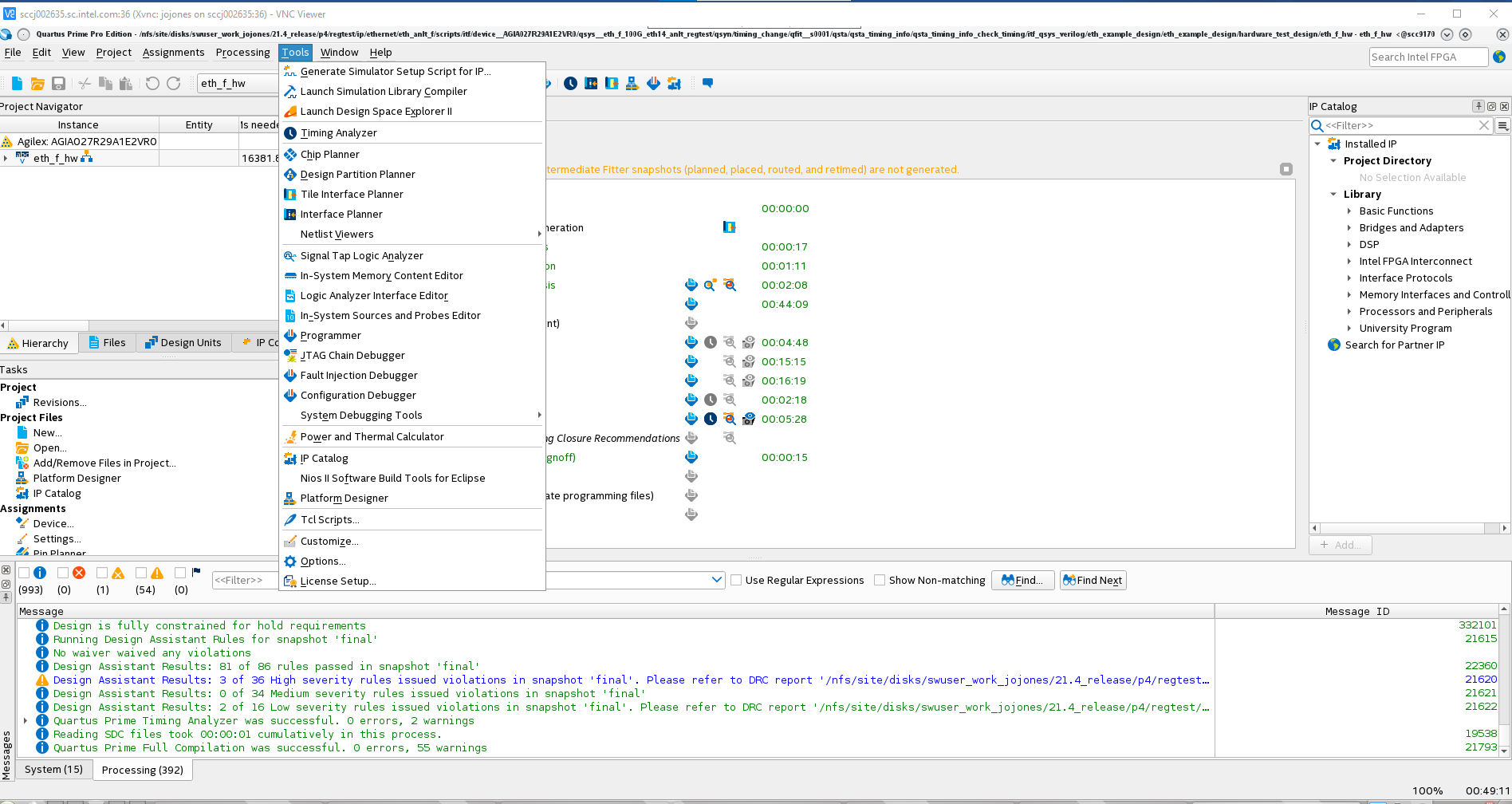
- ) Once you have compiled your design in the Intel® Quartus® Prime Software, launch the Timing Analyzer from the Tools menu.
- ) After the Timing Analyzer has created the timing netlist, generate various timing reports including the setup timing report and the recovery timing report.
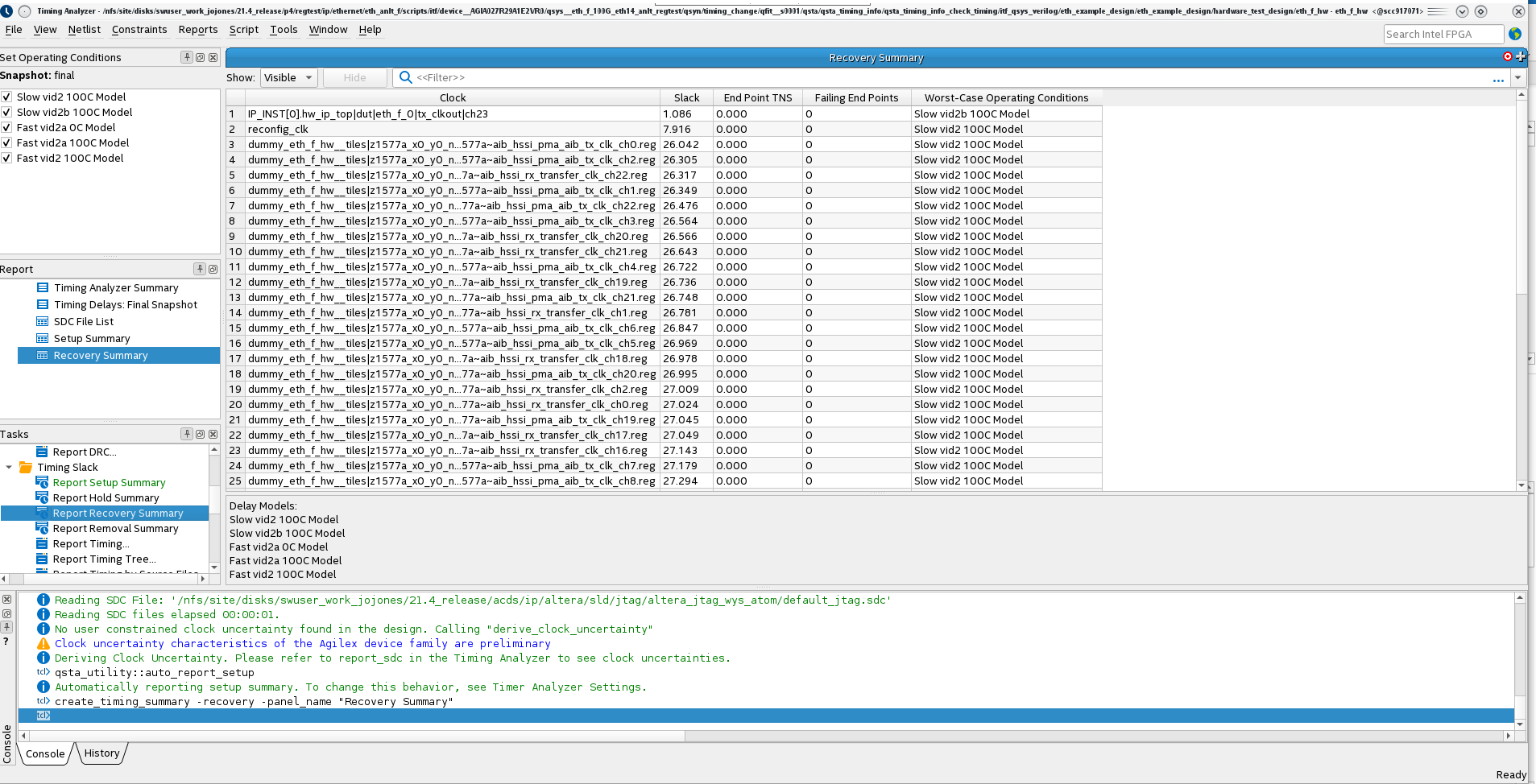
In this case, even though the false paths are not constrained, the timing analyzer does not report any timing errors.
-
) Look at the clock domain crossing report to see the unconstrained timing paths.
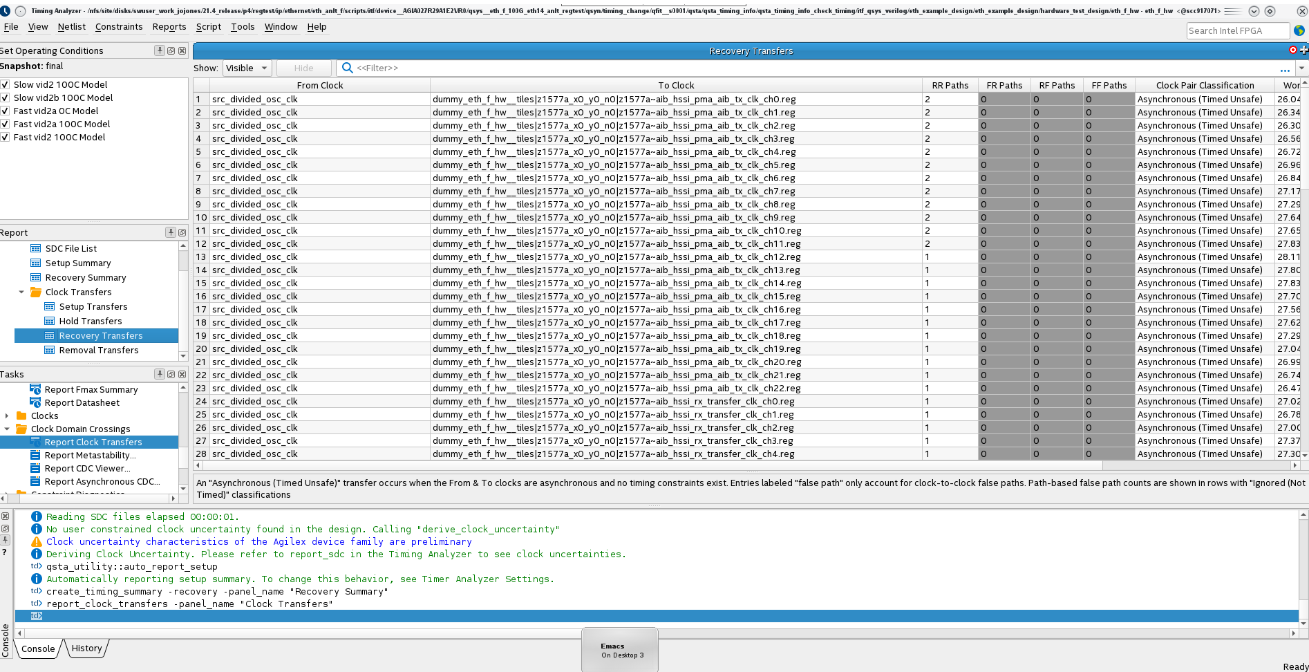 This shows the unconstrained timing paths as Asynchronous (Timed Unsafe). Even though the Timing Analyzer does not report a timing error for these paths, they should be constrained so that they are not included in the timing analysis.
-
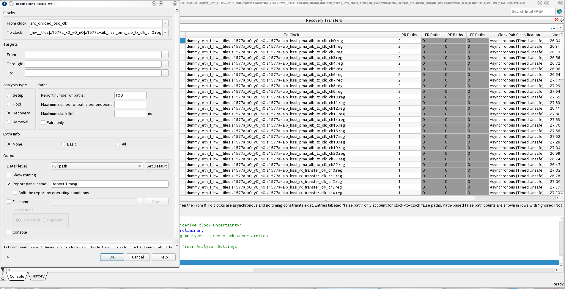
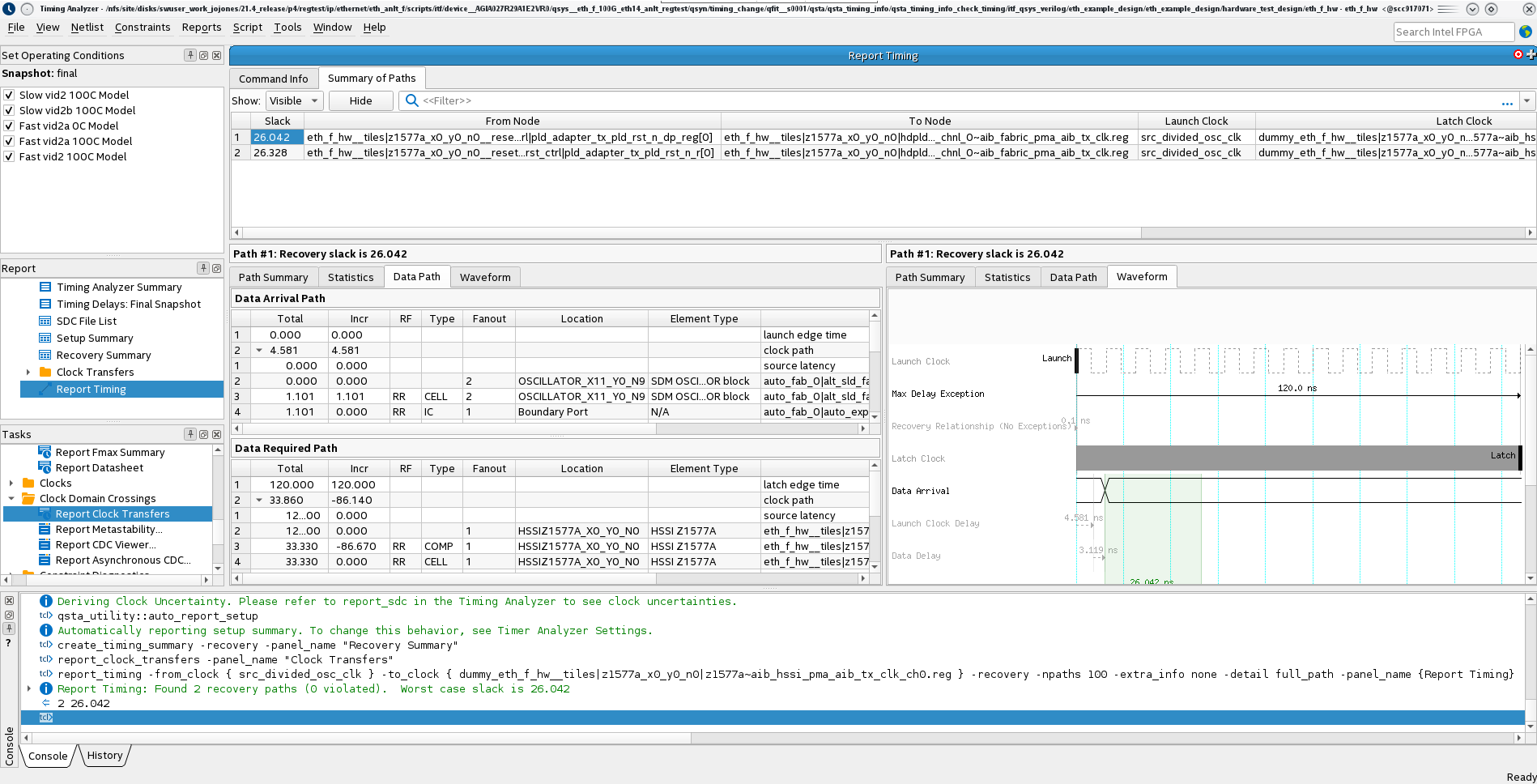
) To set a constraint on these paths, select one of them, right-click the mouse, and select Report Timing. The default options for the report as shown are sufficient.
-
) Click OK. The Timing Report will be generated.
-
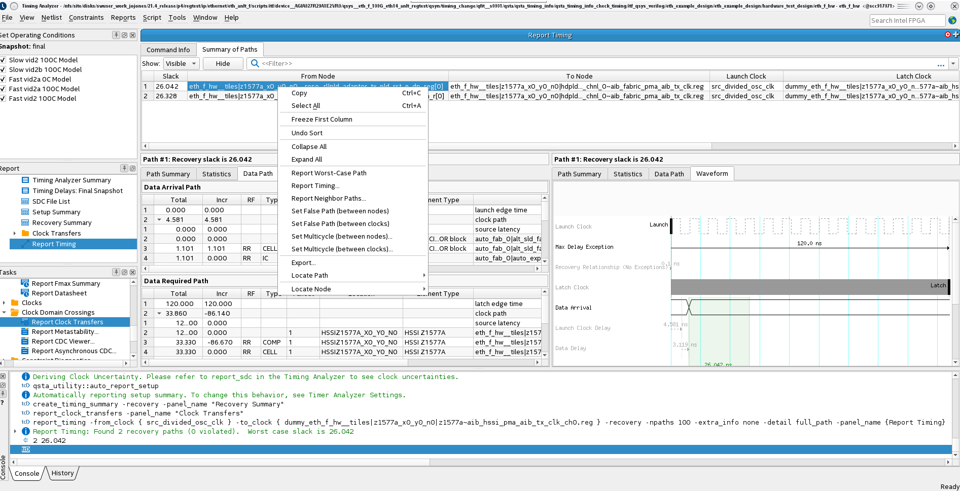
) To constrain the path as a False Path, meaning that it will no longer be included in the timing analysis, right-click anywhere on the path and select Set False Path (between nodes)….
-
) To regenerate the timing reports, right-click on any of the reports shown in the Report window and select Regenerate All Out of Date.
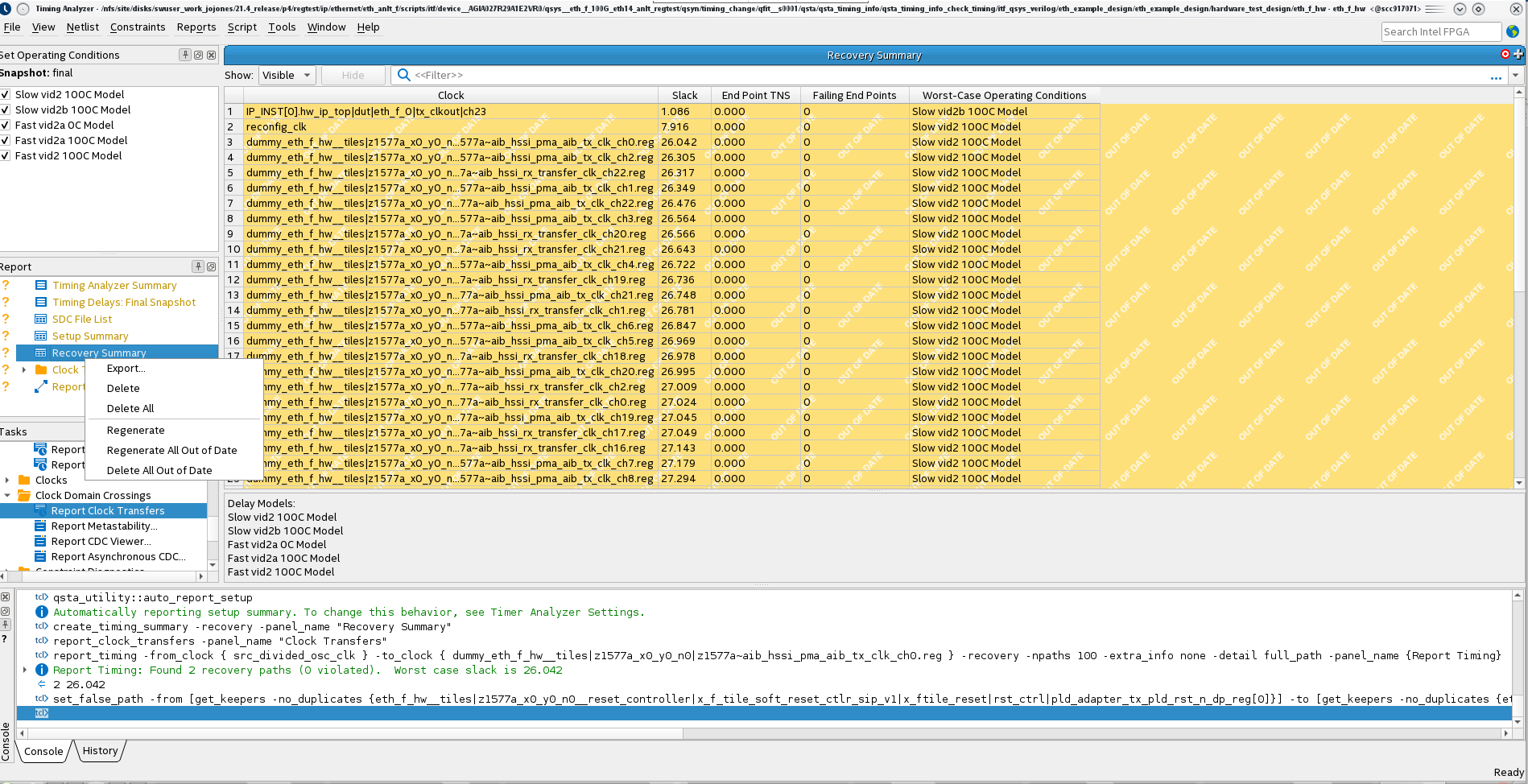 After you regenerate the out-of-date reports, you will see that the timing path you have constrained no longer appears in the summary report. This is because you have constrained the Timing Analyzer to not analyze that false path.
-
) Repeat this for all the paths you want to constrain. When you have finished, save all the changes you have made in a new .sdc file by selecting Write SDC File... from the Constraints menu.
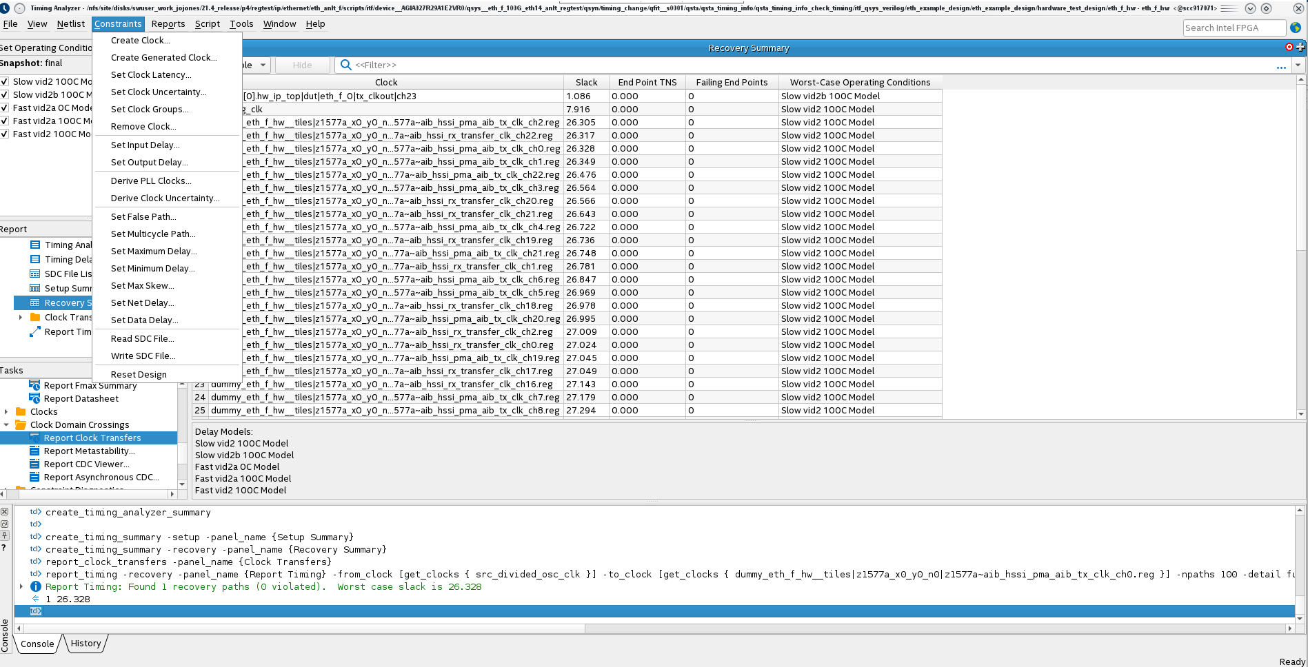
You can select the name and the location of the .sdc file to be written.
The generated .sdc file will include all the constraints from the .sdc files originally read in for the design plus the new constraint you have added.
You can add this .sdc file to your Intel Quartus Prime Software project for future compilations.
This problem is scheduled to be fixed in a future release of the Intel Quartus Prime Pro Edition Software.