An external reset, which is a primary input that is used as a reset signal, should be synchronized in a design (that is, it should drive two cascaded registers before driving one or more input reset ports of other registers).
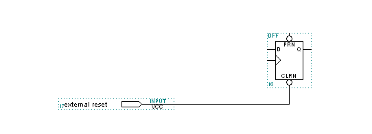
The following image shows an example of an external reset that is not synchronized:

In a design, an asynchronous external reset can affect the recovery time of a register, cause stability problems, and reset state machines to incorrect states.
The synchronized external reset should follow the following guidelines:
- The external reset should be synchronized with two cascaded registers.
- The cascading registers should be triggered on the same clock edge.
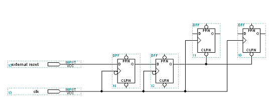
The following image shows an example of a correctly synchronized external reset:

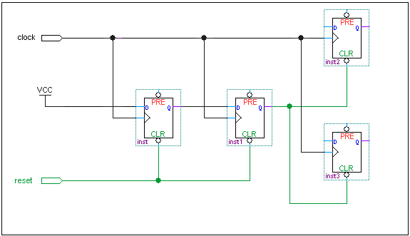
Asynchronous resets are permitted in circumstances where the reset can be released synchronously, most often through the use if of a synchronizer circuit. For example, if your design feeds the reset signal from the cascaded register on the active low CLR port, the D port of the first cascaded synchronizing register must feed the VCC port. The cascaded registers and the reset registers that are fed from the second register in the cascade should all have the same clock source. The following image is an example of an asynchronous synchronizing reset:

The signal from the second cascaded register should feed the active low CLR port of the reset register. This example contains both active high and active low reset synchronization.