Visible to Intel only — GUID: atj1620002805134
Ixiasoft
3.5.2.5.1. Build and Install Netdev Driver
3.5.2.5.2. Enable VFs if SRIOV is Supported
3.5.2.5.3. Configure the Number of Channels Supported on the Device
3.5.2.5.4. Configure the MTU Value
3.5.2.5.5. Configure the Device Communication
3.5.2.5.6. Configure Transmit Queue Selection Mechanism
3.5.2.5.7. Test Procedure by Using Name Space Environment
3.5.2.5.8. PIO Test
Visible to Intel only — GUID: atj1620002805134
Ixiasoft
3.5.2.4.5. Run the Reference Example Application
- After the reference application is built, run it:
$ ./build/mcdma-test -- -h
- This command will display the available options in the application as shown in the image below:
- Do a PIO test to check if the setup is correct. If successful, the application will show a Pass status.
[root@BAPVENC011T perfq]# ./build/mcdma-test -- -b 0000:01:00.0 -o
Here -b should be provided with the correct BDF in the system.
- The DPDK driver can be used with the Avalon-ST Packet Generate/Check design example to test the packet generator and checker design.
The following diagram shows the testing strategy.
Configuration in examples/mcdma-test/perfq/perfq_app.h
In the case of static channel mapping, modify the following parameters:• /* PF count starts from 1 */ #define IFC_QDMA_CUR_PF <pf number> • /* VF count starts from 1. Zero implies PF was used instead of VF */ #define IFC_QDMA_CUR_VF <vf number> • /* Number of PFs */ #define IFC_QDMA_PFS <number of PFs> /* Channels available per PF */ #define IFC_QDMA_PER_PF_CHNLS <number of channels per PF> • /* Channels available per VF */ #define IFC_QDMA_PER_VF_CHNLS <number of channels per VF> • /* Number of VFs per PF */ #define IFC_QDMA_PER_PF_VFS <number of VFs per PF>
perfq_app command line parameters:
Command:$ ./build/mcdma-test -m 8192 --file-prefix=pf0 --\ -b 0000:01:00.0 -p 32768 -d 2 -c 1 -a 2 -l 5 -z -n
Configuration:- 1 channel (-c 1)
- Packet generator bidirectional (-z)
- Payload length of 32,768 bytes in each descriptor (-p 32768)
- Transfer the data every 5 seconds (-l 5)
- Dump the progress log every second (-d 2)
- Configure the number of channels in ED (-n)
- Number of threads to be used for DMA purpose. (-a 2)
Note: This hardware test was run with the Intel® Stratix® 10 GX H-tile PCIe Gen3 x16 configuration.Figure 37. DPDK Avalon-ST Packet Generate/Check Design Example Gen4 x16 : P-Tile Hardware Test Results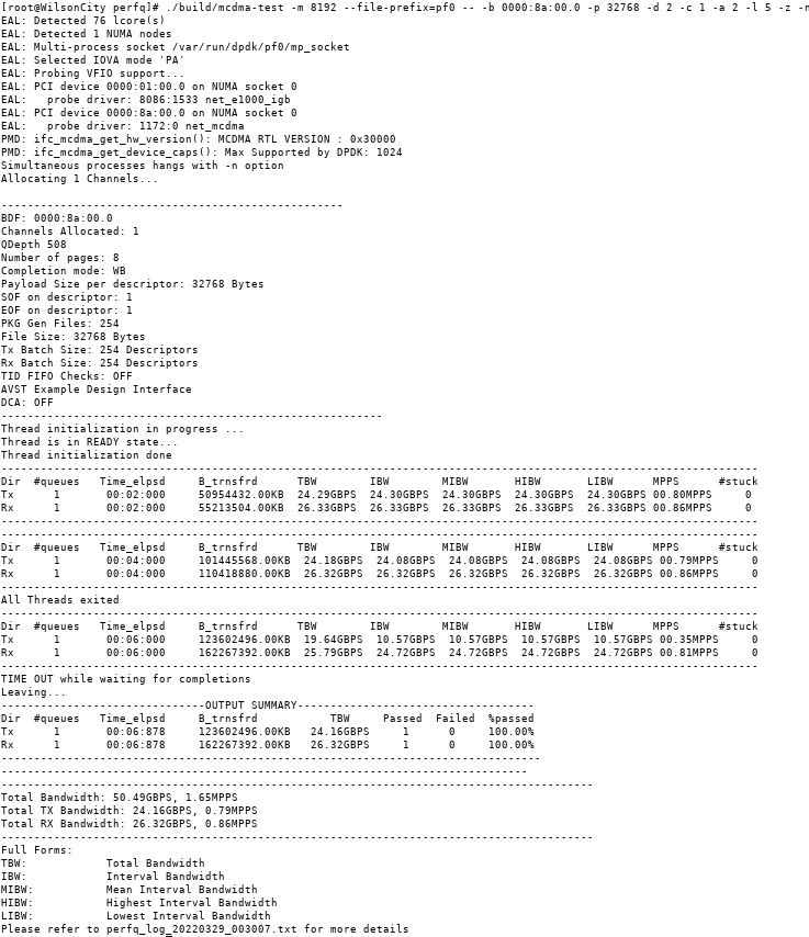
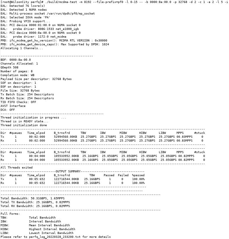
- The DPDK driver can also be used with the Avalon-ST Device-side Packet Loopback design example to test loopback.
The following diagram shows the testing strategy.
Command: $ ./build/mcdma-test -m 8192 --file-prefix=pf0 -l 0-15 -- -b 0000:01:00.0 -p 32768 -d 2 -c 1 -a 2 -l 5 -i
Configuration:- 1 channel (-c 1)
- Packet generator bidirectional (-i)
- Payload length of 64 bytes in each descriptor (-p 32768)
- Transfer the data every 5 seconds (-l 5)
- Dump the progress log every second (-d 2)
Note: This hardware test was run with the Intel® Stratix® 10 GX H-tile PCIe Gen3 x16 configuration.Figure 38. DPDK Avalon-ST Device-side Packet Loopback Design Example Gen4 x16 : P-Tile Hardware Test Result