Visible to Intel only — GUID: hco1433527944316
Ixiasoft
1. About the Drive-On-Chip Design Example for Cyclone V Devices
2. Motor Control Boards
3. Drive-On-Chip Design Example for Cyclone V Devices Features
4. Getting Started
5. Building the Design
6. Debugging and Monitoring the Drive-On-Chip Design Example with System Console
7. About the Scaling of Feedback Signals
8. Motor Control Software
9. Functional Description of the Drive-On-Chip Design Example
10. Achieving Timing Closure on a Motor Control Design
11. Design Security Recommendations
12. Reference Documents for the Drive-on-Chip Design Example
13. Document Revision History for AN 669: Drive-on-Chip Reference Design
4.1. Software Requirements for the Drive-On-Chip Design Example for Cyclone V Devices
4.2. Downloading and Installing the Drive-On-Chip Design Example for Cyclone V Devices
4.3. Setting Up the Motor Control Board with your Development Board
4.4. Programming the Hardware onto the Device
4.5. Setting Up Terminal Emulator
4.6. Downloading the HPS Software to the Device
6.1. System Console GUI Upper Pane for the Drive-On-Chip Design Example
6.2. System Console GUI Lower Pane for the Drive-On-Chip Design Example
6.3. Vibration Suppression Tab
6.4. Controlling the DC-DC Converter
6.5. Tuning the PI Controller Gains
6.6. Controlling the Speed and Position Demonstrations
6.7. Monitoring Performance
9.1. Processor Subsystem
9.2. Six-channel PWM Interface
9.3. DC Link Monitor
9.4. Drive System Monitor
9.5. Quadrature Encoder Interface
9.6. Sigma-Delta ADC Interface for Drive Axes
9.7. DC-DC Converter
9.8. Motor Control Modes
9.9. FOC Subsystem
9.10. FFTs
9.11. DEKF Technique for Battery Management
9.12. Signals
9.13. Registers
9.9.1. DSP Builder for Intel FPGAs Model for the Drive-On-Chip Designs
9.9.2. Avalon Memory-Mapped Interface
9.9.3. About DSP Builder for Intel FPGAs
9.9.4. DSP Builder for Intel FPGAs Folding
9.9.5. DSP Builder for Intel FPGAs Model Resource Usage
9.9.6. DSP Builder for Intel FPGAs Design Guidelines
9.9.7. Generating VHDL for the DSP Builder Models for the Drive-On-Chip Reference Designs
Visible to Intel only — GUID: hco1433527944316
Ixiasoft
Downloading the DS-5 HPS Software to the Device
Import and compile the HPS software in DS-5. You must have a DS-5 debugger license to download HPS software.
- Select Run > Debug Configurations.
- Create new DS-5 debugger configuration:
- Right click on the DS-5 Debugger launch type
- Select New.
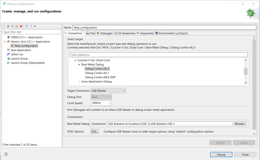
- On the Connection tab, select Debug Cortex-A9_0 under Cyclone V SoC (Dual Core)|Bare Metal Debug.
- In the Target Connection drop-down select USB-Blaster.
- In the Bare Metal Debug Connection field, click Browse… and select the USB Blaster II on localhost (or CV SoCKit on localhost for the SoCKit).
Figure 4. Connection Tab
- Select the Debugger tab.
- In Run Control, select Connect Only.
- In Host working directory turn off Use default and change the path to ${workspace_loc:/DOC_CVSX} by clicking Workspace and selecting DOC_CVSX
- Click Apply to save the configuration, optionally specifying a name for the new configuration.
- Click Debug.
- Click Yes when the application asks you to switch to debug perspective.
- In the Command text field enter the command source debug.ds.
- Click Submit to load and run the preloader then load the application and run to main().
- Click Continue (green arrow) to run the application.
- Check that the terminal console display shows the correct FPGA and power board combination. For example:
0: [DECODE SYSID] Decoding hardware platform from QSYS SYSID data : 0x00D112FE 0: [DECODE SYSID] Design Version : 15.0 0: [DECODE SYSID] FPGA Board : Cyclone V SX SoC Dev Kit 0: [DECODE SYSID] Power Board : FalconEye v2.0 HSMC Single-axis 0: [DECODE SYSID] Encoder Type : EnDat 0: [DECODE SYSID] 1 axes available 0: [DECODE SYSID] Axis 0 : Enabled - When the application is running, right-click on Cortex-A9_0 and click Disconnect from Target.
- Apply power to the power board. The motor starts to turn.