Introduction
Implementing artificial intelligence with the Unity* software game engine and showing an emergent behavior as crowd simulation is one of the best ways you can create simulations. In this article, we go through the process of creating a crowd simulation in Unity software and then realizing it as a mixed reality application.
The steps that we’ll go through are as follows:
- Implementing artificial intelligence with Unity software.
- Building a crowd simulation in Unity software.
- Creating a mixed reality build of the project.
System Requirements
The following is the configuration we used for this project:
- Standard ASUS ROG* laptop
- 4th Generation Intel® Core™ i7 processor
- 8 GB RAM
- Windows® 10 Enterprise edition
Crowd Simulation
In this article, we discuss a behavior known as crowd simulation, which we will create in Unity software. The objects that define the behaviors required to implement the crowd artificial intelligence (AI) are known as agents. In this case, we are concerned with agents on a mass scale, rather than an individual basis. We’ll take a look at different behaviors arising from the crowd simulation, such as motion, collision, direction, and speed propagation from one person to another, which gives the group its own identity.
To simulate every individual in a crowd and produce group behavior is labor intensive, requiring a large number of decisions for individuals and objects in a crowd, all predicated on behaviors that can be implemented using simple vector methods.
Many different methods have been used for formulating crowd behavior. Crowds don’t move chaotically but are more organized than is immediately apparent. They can be self-organized systems with flow lines appearing in the direction of movement.
The more dense a crowd becomes, the higher the chance that turbulence will occur. One of the simplest ways to simulate crowd behavior is to implement Reynolds’ flocking algorithm.
In 1986, Craig Reynolds created a simulated model that produces a behavior similar to the way that flocks of birds and schools of fish behave. The simulations used invented flocking creatures called boids.
In most cases we see the boid as an example of emergent behavior.
Reynolds’ algorithm is based upon three simple steering behaviors for the simulated boids.
- Separation: Steering to avoid other boids crowding nearby.
- Cohesion: Steering to move forward toward the average position of other nearby boids.
- Alignment: Steering toward the average heading of other nearby boids.
We will be implementing and combining these behaviors in Unity software using navigation meshes (navmeshes) and ray casting to create the desired effects.
Getting Started
We’ll first use the Unity software integrated development environment (IDE) to implement the artificial intelligence behavior of objects and show how the emergent behavior works. Then we will convert the project build into a mixed reality application, and see how mixed reality Windows® 10 Universal Windows Platform (UWP) is created.
Step 1: Creating the project
For the first step we need to open up a project in Unity software and then get started by creating the project requirements.
Step 2: Declaring objects in the scene
Next, we create a scene in Unity software with the required objects to be used. We’ll use 3D objects for this project.
Step 3: Creating behavior for artificial intelligence in Unity software
In this step, we create a scene requirement that replicates a crowd simulation in Unity software. The basis for the crowd simulation in this scene is a red agent and a blue agent which, as objects are given the ability to move from one place to another, replicate crowd behavior.
Step 4: Setting up our PC for mixed reality
Next, set up your computer for Windows 10 mixed reality applications, so that if you don’t have a mixed reality headset, you can experience the next best thing with a simulated mixed reality environment.
Step 5: Building the scene and turning it into a mixed reality application
In this step, we’ll create a scene and then create a build of it as a Windows Mixed Reality application using IL2CPP* scripting on the back end to run the application. There are intermediate steps that are important to pay attention to, such as converting the build using appropriate settings so that the project is optimized for Windows 10 UWP. When creating the build for the project we need to select the IL2CPP back end so that the size of the simulated environment and its running speed are optimized. When we generate the build for the project, a Microsoft Visual Studio* solution file is created, the structure of which is covered in this piece. Finally, the native build is generated so that it runs perfectly as a Windows 10 mixed reality application.
Creating the Project in Unity* Software IDE and Declaring Objects in the Scene
To get the scene rolling we’ll start by creating a new project.
First, we open up Unity software IDE. Next, we create a new project and name it “New Unity Project (5)”.
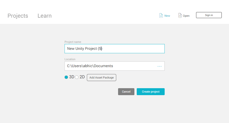
Figure 1. Creating the new project called New Unity Project (5).
Save the scene as scene2.
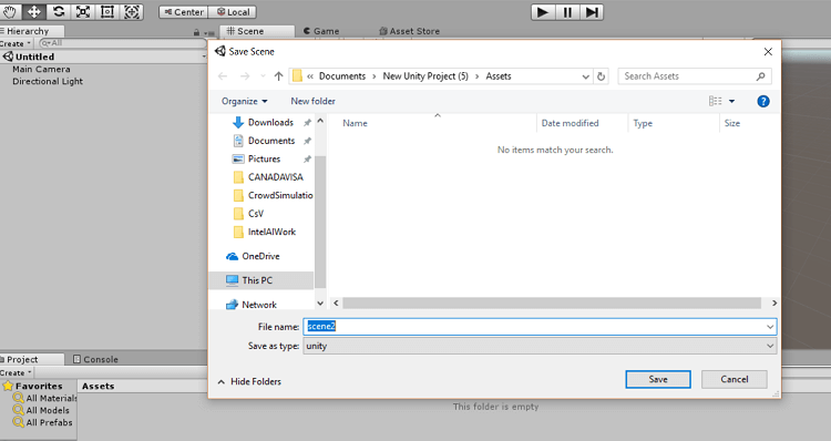
Figure 2. Saving the scene as “scene2”.
Next, we’ll add game objects to our scene.
First, we add a plane, then we stretch it as needed. Then, we add a new cube-shaped 3D object that will function as walls.
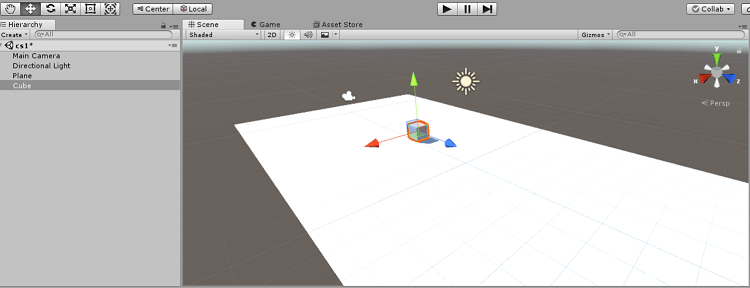
Figure 3. Adding a plane to the scene and adding a first 3D cube.
After adding two cubes we adjust them as needed.
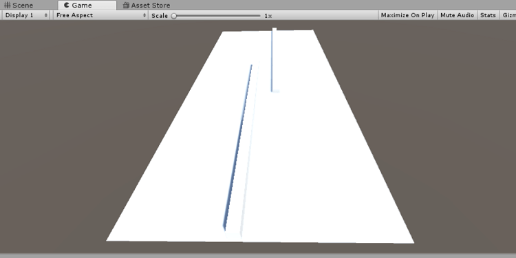
Figure 4. Stretching the cubes to create walls.
We rename the cubes as walls and add colors to the walls to make them more visible. To do that, we need to declare a new material.
After adding colors to the walls, the scene looks something like the image below.

Figure 5. Adding color to the walls.
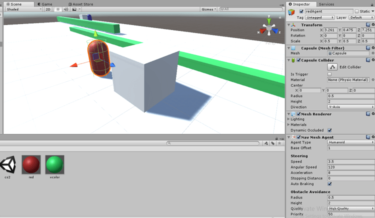
Next, we add capsules to recognize the agents. We reduce the scale of the capsules to 0.5 and 0.5, and rename the capsules as red agent and blue agent, respectively.
The next stage is to create material and add the colors red and blue. For the goal points for the red and blue agents we need to create two cubes. Once we’ve added the cubes and capsules to the scene, it should look like this.
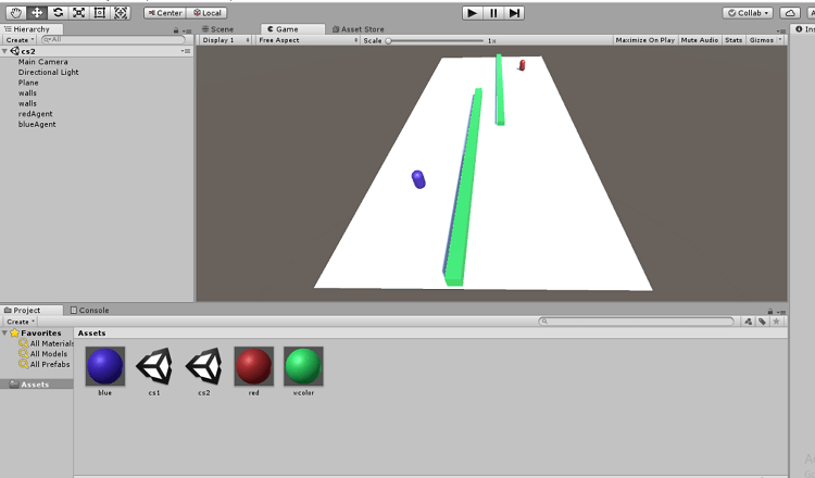
Figure 6. Adding red and blue agents.
We need to rename the cubes as redGoal and blueGoal.
Next, we need to add navmesh to both the red and blue agents. To do so, we click on add component and then add the default navmesh.

Figure 7. Adding “navmesh” to the red and blue agents.
Then create a C# script named “AIController.cs”. Let’s take a look at the default script:
using System.Collections;
using System.Collections.Generic;
using UnityEngine;

public class AIController : MonoBehavior {

    // Use this for initialization
    void Start () {

    }

    // Update is called once per frame
    void Update () {

    }
}
Once we’ve added in the required values, the script changes to the following:
using System.Collections;
using System.Collections.Generic;
using UnityEngine;
using UnityEngine.AI;

public class AIController : MonoBehavior {
    public GameObject goal;
    NavMeshAgent agent;


    // Use this for initialization
    void Start () {
        agent = this.GetComponent<NavMeshAgent> ();
        agent.SetDestination (goal.transform.position);

    }

    // Update is called once per frame
    void Update () {

    }
}
Next, we add this script to both the red agent and the blue agent. Both the capsule goals are opposites to each other.
Creating Behaviors for AI
Setting up the navigation for navmeshes
To apply the appropriate behaviors to the agents, we need to adjust some settings.
Adding custom tabs
To add navigation tabs alongside the Inspector panel and services, go to the Windows tab and select Navigation.
Then we need to name certain objects in the scene as navigation static. For that, we select certain objects, namely the plane and the walls.
Once that’s set up we need to go to the Bake tab and click on Bake.
Further adjustments need to be made on the AI script. We need to choose a goal, as we see in the AI script attached to both the blue and red agents.
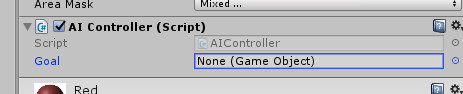
Figure 8. Choosing a goal for the red and blue agents.
Next, we select the goal for both the red and blue agents simultaneously, and then we play the scene. To replicate more agents, we simply copy the agents (control + B) to create a crowd simulation.
To select the red agent, hit control + D on the keyboard ten times, then do the same for the blue agents.
Building for Mixed Reality
We’re using Unity 4.2 for development. To create a mixed reality build we need to make certain changes.
Windows Mixed Reality
Windows Mixed Reality is a mixed reality platform that combines augmented reality with the effect of a head-mounted display to deliver a unique experience. The mixed reality application is a Windows 10 UWP app that runs on head-mounted displays.
The mixed reality platform has been around since the April 2018 Windows 10 Creators Update, which is required for mixed reality development.
Required tools
The preparation list for using a mixed reality headset is quite long as there are many things that need to be installed. These include:
Microsoft Visual Studio 2017
To install, select the Universal Windows Platform and the Game Development with Unity software options. Ensure that hyper-v is enabled and that the version of Unity software used is Unity 2017.4.
Since we need to install the IL2CPP backend while installing Microsoft Visual Studio 2017, choose the Desktop Development with C++ option.
Setting Up the Project for Mixed Reality
First, go to the build settings, then select Universal Windows Platform.
Target Device: select Any device or HoloLens*.
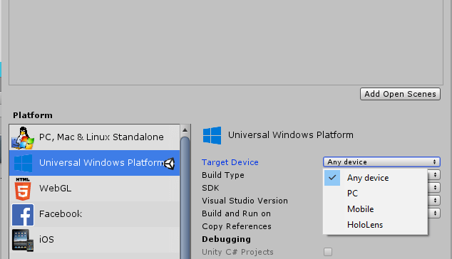
Figure 9. Selecting Any device for the Universal Windows* Platform build settings.
Settings we need to keep are:
Build type -> Direct3D*
SDK -> Latest installed
Microsoft Visual Studio version -> Latest installed
Build and run on -> Local machine
Since we are developing for an immersive mixed reality-based application that has an immersive view instead of the regular 2D or 3D view, we then need to enable virtual reality. Here’s how we do that.
First, ensure you are in the Universal Windows Platform. Go to Build Settings, then select Player Settings, then select XR Settings.
In XR settings, make sure that Virtual Reality and Windows Mixed Reality are supported.
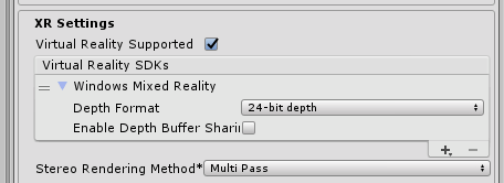
Figure 10. Configuring Windows* Mixed Reality to enable VR settings.
Next, go to the publishing settings and add a name in the Package Options.
Package name ->Abhishek nandy
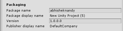
Figure 11. Naming the package to prepare for publishing.
In the Capabilities option set Immersive Quality Headsets, Spatial Perception, WebCam, and Microphone.
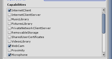
Figure 12. Configuring capabilities supported by the project.
In Unity software camera settings, set RGBA to 0.
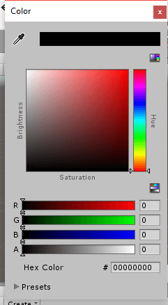
Figure 13. Selecting Unity* software camera settings, setting RGBA to 0.
Next, we compile the scene in this manner:
Add the required scene. In this case “scene3”, then click Build. Before the final native file is created, we need to set a few Windows settings, then click Update & Security.
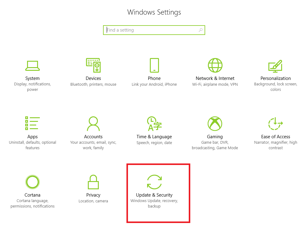
Figure 14. Configuring Windows* settings for Update & Security.
On the left-hand side we need to select the For developers option.
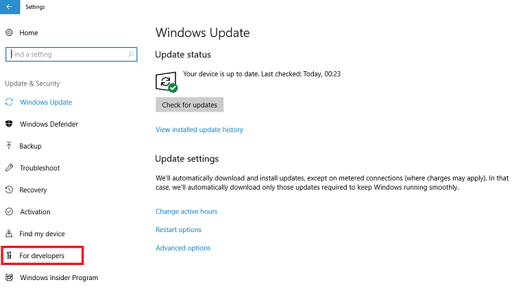
Figure 15. Configuring the “For developers” option.
Make sure Developer mode is selected and the developer mode package is installed.
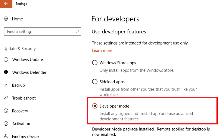
Figure 16. Selecting Developer mode to enable advanced development features.
In the search field, type mixed reality portal.
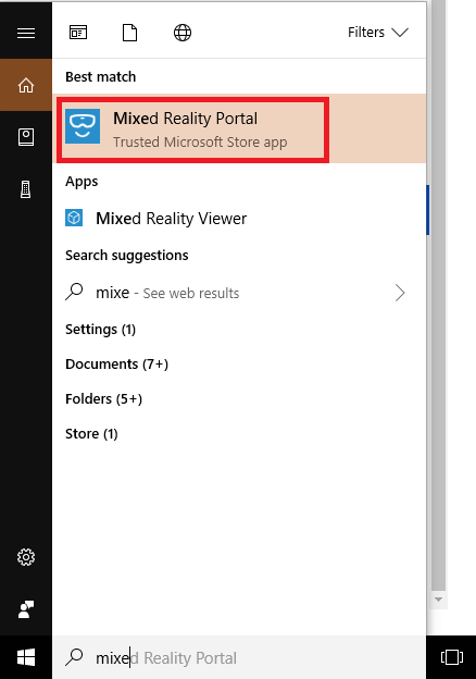
Figure 17. Adding “Mixed Reality Portal” to the build options.
When the Mixed Reality Portal is selected, you will see the Get Started button. Click that.
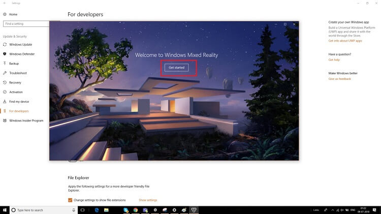
Figure 18. Getting Started screen for Windows* Mixed Reality.
This is where you see the terms and conditions that you need to accept.
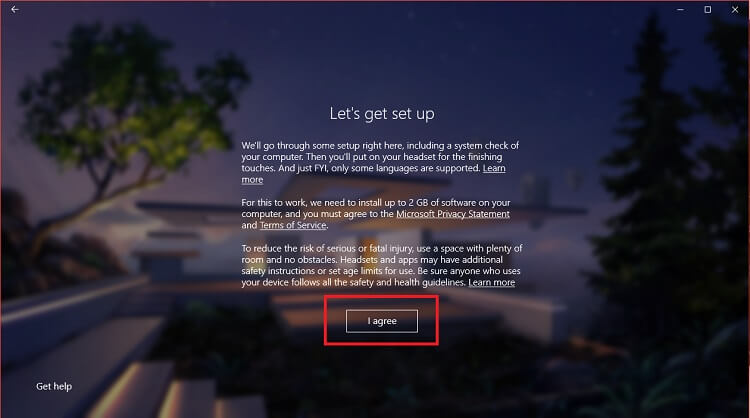
Figure 19. Acknowledging terms of service and safety warnings.
The next page displays the system configuration of your PC so you can see if you meet the criteria. Click the Simulated option.
When you click Next you get the option that shows you are set up with Windows Mixed Reality.
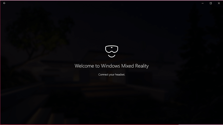
Figure 20. Welcome screen for Windows* Mixed Reality.
Select Set up simulation (for developers).
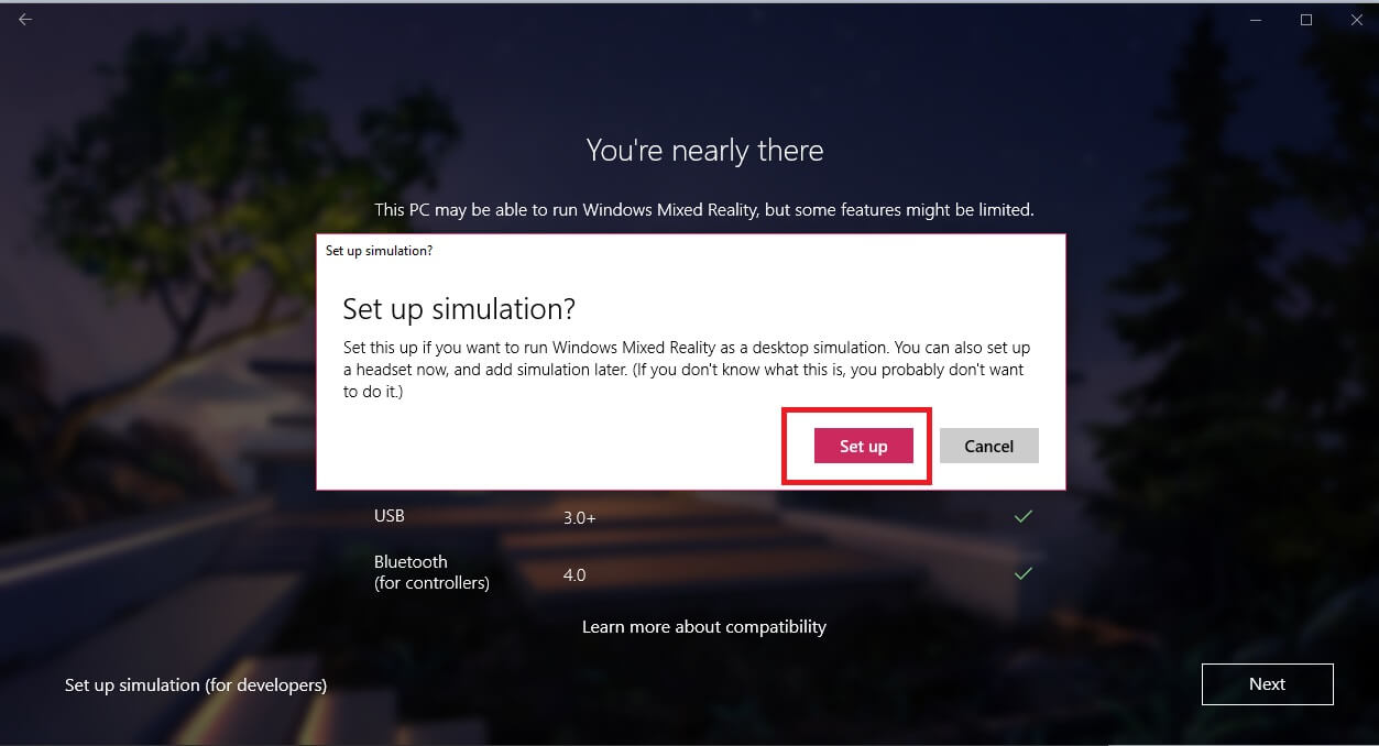
Figure 21. Setting up the desktop simulation for Windows* Mixed Reality.
A download of additional content for Mixed Reality follows.
Figure 22. Downloading additional content for Windows* Mixed Reality.
Building for Windows® 10 UWP and Mixed Reality
Click on the file, then build settings\ in Unity software, then go to the player settings for Universal Windows Platform. In the Configuration pane you can choose between .NET core or IL2CPP. Select IL2CPP (Intermediate Level C++).
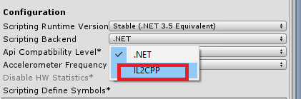
Figure 23. Setting the scripting backend option to IL2CPP*.
Next, select the scene; in this case Scene 2, then click Build.
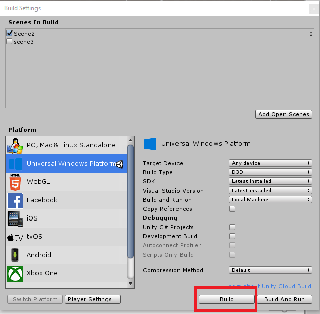
Figure 24. Preparing to build Scene2.
Select a folder on your computer where you will store the files. A Microsoft Visual Studio solution file is generated in the order of every possible build.
Since we named this project New Unity Project (5), the generated solution file is given the name “New Unity Project (5).soln”.
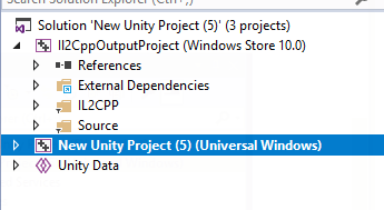
Figure 25. The new solution file adopts the name of the Unity* software project.
Before digging deep into the solution file, we need to better understand IL2CPP.
What is IL2CPP*?
If you want an alternative to .NET when compiling for UWP, IL2CPP is the best option.
When building the Unity software project for UWP, Unity software converts IL (intermediate level) code and different assemblies to C++ before creating the native library. The native binary files created are .exe, .apk, and .xap.
For the Unity software game engine, the project or the game output may be bigger in size; to reduce the size of the game we use IL2CPP.
With IL2CPP we convert the Unity scripting API code to managed assemblies.
The additional plugins and libraries used with IL2CPP are processed by a Unity software tool called unused bytecode stripper, which locates all the unused classes and methods and removes them from the DLLs. All the managed assemblies are then converted to standard C++ code.
The code generated for C++ and the runtime part of IL2CPP is then compiled using a native platform compiler, as shown in the figure below.
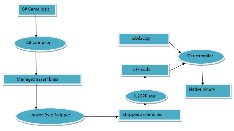
Figure 26. Flowchart for converting to C++ code and compiling into a native binary.
The Microsoft Visual Studio* solution file
Let’s go back and take a look at the Microsoft Visual Studio solution file. First, we’ll look at the important header files:
the app.h files and #pragma once

namespace New_Unity_Project__5_
{
    ref class App sealed :
        public Windows::ApplicationModel::Core::IFrameworkView,
        public Windows::ApplicationModel::Core::IFrameworkViewSource
    {
    public:
        virtual void Initialize(Windows::ApplicationModel::Core::CoreApplicationView^ applicationView);
        virtual void SetWindow(Windows::UI::Core::CoreWindow^ window);
        virtual void Load(Platform::String^ entryPoint);
        virtual void Run();
        virtual void Uninitialize();

        virtual Windows::ApplicationModel::Core::IFrameworkView^ CreateView();

    private:
        UnityPlayer::AppCallbacks^ m_AppCallbacks;
        Windows::UI::Core::CoreWindow^ m_CoreWindow;
        void OnActivated(Windows::ApplicationModel::Core::CoreApplicationView^ sender, Windows::ApplicationModel::Activation::IActivatedEventArgs^ args);
        void SetupOrientation();
    };
}
In the main.cpp we initialize the wrapper that converts the C# code to C++.
#include "pch.h"
#include "App.h"

struct RoInitializeWrapper
{
    inline RoInitializeWrapper() { RoInitialize(RO_INIT_MULTITHREADED); }
    inline ~RoInitializeWrapper() { RoUninitialize(); }
};

int CALLBACK wWinMain(HINSTANCE hInstance, HINSTANCE hPrevInstance, LPWSTR lpCmdLine, int nCmdShow)
{
    RoInitializeWrapper roInit;

    Windows::ApplicationModel::Core::CoreApplication::Run(ref new New_Unity_Project__5_::App());
    return 0;
}
From the class sealed app.h file, we derive the core capabilities of the app, which then initializes the Unity software framework. The files are created automatically.
The header pch.h is used for the standard system files that are to be used in the project.
#pragma once
#include <roapi.h>
#include <Windows.h>
The generated app.cpp file contains all the handlers and main capabilities to run the app in the Windows UWP environment. The generated code is shown below:
#include "pch.h"
#include "App.h"
#include "UnityGenerated.h"

using namespace New_Unity_Project__5_;
using namespace Platform;
using namespace UnityPlayer;
using namespace Windows::ApplicationModel::Activation;
using namespace Windows::ApplicationModel::Core;
using namespace Windows::Foundation;
using namespace Windows::UI::Core;
using namespace Windows::UI::ViewManagement;

void App::Initialize(CoreApplicationView^ applicationView)
{
    SetupOrientation();
    m_AppCallbacks = ref new AppCallbacks();
    m_AppCallbacks->SetCoreApplicationViewEvents(applicationView);
    applicationView->Activated += ref new TypedEventHandler<CoreApplicationView ^, IActivatedEventArgs^>(this, &App::OnActivated);
}

void App::SetWindow(CoreWindow^ window)
{
    m_CoreWindow = window;

    ApplicationView::GetForCurrentView()->SuppressSystemOverlays = true;

    m_AppCallbacks->SetCoreWindowEvents(window);
    m_AppCallbacks->InitializeD3DWindow();
}

void App::Load(String^ entryPoint)
{
}

void App::Run()
{
    m_AppCallbacks->Run();
}

void App::Uninitialize()
{
    m_AppCallbacks = nullptr;
}

IFrameworkView^ App::CreateView()
{
    return this;
}

void App::OnActivated(CoreApplicationView^ sender, IActivatedEventArgs^ args)
{
    m_CoreWindow->Activate();
}

void App::SetupOrientation()
{
    Unity::SetupDisplay();
}
Next, the solution file needs to be compiled, then you can build the app for Windows Mixed Reality. For Microsoft Visual Studio, we need to select to run locally and then double-click the deployed project. It then runs on the mixed reality platform with the selected simulated option.
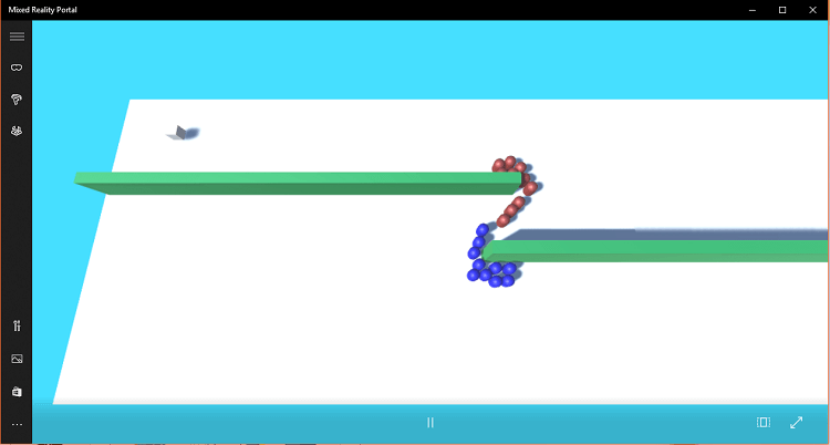
Figure 27. Running the completed simulation project.
Summary
With this project using the Unity software game engine, we started to learn about the creation of a crowd simulation to demonstrate flocking as an emergent behavior. In the process, we created a fully-fledged mixed reality application for Windows.